HEATING / AIR CONDITIONING AIR CONDITIONING PANEL INSTALLATION
PROCEDURE

 84730 1.INSTALL HEATER BLOWER SWITCH ASSEMBLY
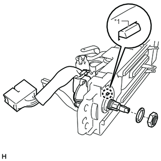
| *1 | Guide |
Install the heater blower switch assembly with the nut and washer as shown in the illustration.
84732A 2.INSTALL REAR HEATER BLOWER SWITCH (w/ Rear Heater)
55910 3.INSTALL HEATER OR BOOST VENTILATOR CONTROL ASSEMBLY
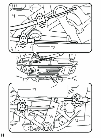
| *A | w/ Heater |
| *1 | Air Inlet Damper Control Cable Sub-assembly (Black) |
| *2 | Defroster Damper Control Cable Sub-assembly (Black) |
| *3 | Water Valve Control Cable Sub-assembly (Blue) |
| *4 | Airmix Damper Control Cable Sub-assembly (Black) |
Install the heater or boost ventilator control assembly.
Attach the 2 claws to install the airmix damper control cable sub-assembly.
w/o Heater:
Install the air inlet damper control cable sub-assembly and defroster damper control cable sub-assembly as shown in the illustration.
w/ Heater:
Install the air inlet damper control cable sub-assembly, defroster damper control cable sub-assembly and water valve control cable sub-assembly as shown in the illustration.
w/o Heater:
Attach the 4 claws to install the 2 heater control cable clamps.
w/ Heater:
Attach the 6 claws to install the 3 heater control cable clamps.
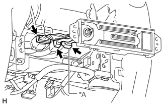
| *A | w/ Rear Heater |
w/o Rear Heater:
Connect the 2 connectors.
w/ Rear Heater:
Connect the 3 connectors.
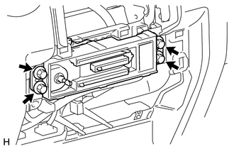
Install the 4 bolts.
- Torque:
- 5.0 N*m (51 kgf*cm, 44 in.*lbf)
81942 4.INSTALL HEATER CONTROL NAME SHEET
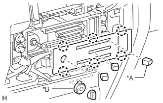
| *A | w/ Heater |
| *B | w/ Cooler System |
Attach the 6 claws to install the heater control name sheet.
w/o Cooler System:
Install the heater blower switch knob.
w/ Cooler System:
Install the heater blower switch knob and cooler switch knob.
w/o Heater:
Install the 2 control knob sub-assemblies.
w/ Heater:
Install the 3 control knob sub-assemblies.
55413D 5.INSTALL CENTER LOWER INSTRUMENT CLUSTER FINISH PANEL
55412D 6.INSTALL CENTER INSTRUMENT CLUSTER FINISH PANEL