EXTERIOR PANELS / TRIM QUARTER PANEL WHEEL OPENING MOULDING(for Model Code #J76 Series) INSTALLATION
CAUTION / NOTICE / HINT
- HINT:
-
·
Use the same procedures for the RH and LH sides.
·The procedures listed below are for the LH side.
·A bolt without a torque specification is shown in the standard bolt chart.
Click hereGeneral>SPECIFICATIONS>STANDARD BOLT>SPECIFIED TORQUE FOR STANDARD BOLTS
PROCEDURE

 61698F 1.INSTALL REAR NO. 4 WHEEL OPENING BRACKET FRONT LH
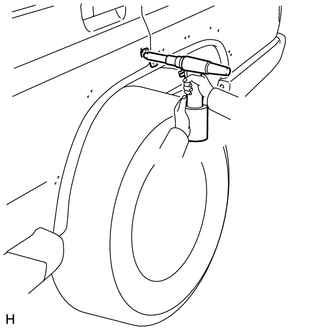
Install the bracket with 2 new rivets.
Using an air riveter or hand riveter with a nose piece, install the rear No. 4 wheel opening bracket front LH with 2 new rivets.
- HINT:
-
If the rivet cannot be cut, pull it once and cut it.
- NOTICE:
-
·
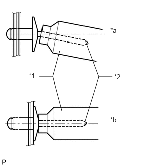 1.229,1.042 1.083,1.573 1.083,1.573 1.271,2.281 false 1.083,1.573 0.813,1.573 false 1.75,0.833 2.031,1.583 2.031,1.583 1.74,2.521 false 2.031,1.573 2.313,1.573 false 2.271,0.542 2.469,0.74 0.198,0.198 10 false *a 2.271,2.385 2.49,2.583 0.219,0.198 10 false *b 0.594,1.479 0.781,1.677 0.188,0.198 10 false *1 2.354,1.5 2.542,1.677 0.188,0.177 10 false *2
*1 Riveter *2 Mandrel *a INCORRECT *b CORRECT
Do not pry the rivet with the riveter, as this will cause damage to the riveter and mandrel.
·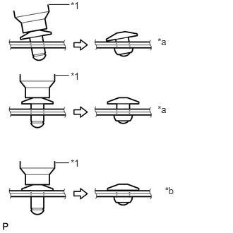 2.325,0.536 2.513,0.713 0.189,0.177 10 *a 2.325,1.527 2.5,1.705 0.175,0.177 10 *a 2.434,2.73 2.634,2.907 0.2,0.177 10 *b 0.72,0.066 1.023,0.066 false 0.818,1.11 1.018,1.11 false 1.043,2.324 1.223,2.477 0.181,0.153 10 *1 1.043,1.044 1.223,1.196 0.181,0.153 10 *1 1.043,0.0040 1.223,0.157 0.181,0.153 10 *1 0.818,2.402 1.018,2.402 false
*1 Riveter *a INCORRECT *b CORRECT
Confirm that the rivets are seated properly against the bracket.
·Do not tilt the riveter when installing the rivet to the bracket.
·Do not leave any space between the rivet head and bracket.
·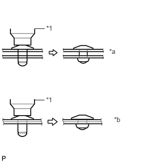 2.304,0.996 2.504,1.173 0.2,0.177 10 *a 2.408,2.434 2.62,2.612 0.211,0.177 10 *b 0.978,0.515 1.173,0.686 0.195,0.171 10 *1 0.735,0.603 0.941,0.603 false 0.973,2.023 1.182,2.194 0.209,0.171 10 *1 0.731,2.111 0.937,2.111 false
*1 Riveter *a INCORRECT *b CORRECT
Do not leave any space between the bracket and door. Firmly hold together the 2 items while installing the rivet.
61695D 2.INSTALL REAR NO. 3 WHEEL OPENING BRACKET FRONT LH
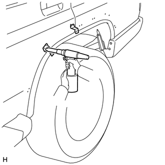
Install the rear No. 3 wheel opening bracket front LH with 2 new rivets.
Using an air riveter or hand riveter with a nose piece, install the rear No. 3 wheel opening bracket front LH with 2 new rivets.
- HINT:
-
If the rivet cannot be cut, pull it once and cut it.
- NOTICE:
-
·
1.229,1.042 1.083,1.573 1.083,1.573 1.271,2.281 false 1.083,1.573 0.813,1.573 false 1.75,0.833 2.031,1.583 2.031,1.583 1.74,2.521 false 2.031,1.573 2.313,1.573 false 2.271,0.542 2.469,0.74 0.198,0.198 10 false *a 2.271,2.385 2.49,2.583 0.219,0.198 10 false *b 0.594,1.479 0.781,1.677 0.188,0.198 10 false *1 2.354,1.5 2.542,1.677 0.188,0.177 10 false *2
*1 Riveter *2 Mandrel *a INCORRECT *b CORRECT
Do not pry the rivet with the riveter, as this will cause damage to the riveter and mandrel.
·
2.325,0.536 2.513,0.713 0.189,0.177 10 *a 2.325,1.527 2.5,1.705 0.175,0.177 10 *a 2.434,2.73 2.634,2.907 0.2,0.177 10 *b 0.72,0.066 1.023,0.066 false 0.818,1.11 1.018,1.11 false 1.043,2.324 1.223,2.477 0.181,0.153 10 *1 1.043,1.044 1.223,1.196 0.181,0.153 10 *1 1.043,0.0040 1.223,0.157 0.181,0.153 10 *1 0.818,2.402 1.018,2.402 false*1 Riveter *a INCORRECT *b CORRECT
Confirm that the rivets are seated properly against the bracket.
·Do not tilt the riveter when installing the rivet to the bracket.
·Do not leave any space between the rivet head and bracket.
·
2.304,0.996 2.504,1.173 0.2,0.177 10 *a 2.408,2.434 2.62,2.612 0.211,0.177 10 *b 0.978,0.515 1.173,0.686 0.195,0.171 10 *1 0.735,0.603 0.941,0.603 false 0.973,2.023 1.182,2.194 0.209,0.171 10 *1 0.731,2.111 0.937,2.111 false*1 Riveter *a INCORRECT *b CORRECT
Do not leave any space between the bracket and door. Firmly hold together the 2 items while installing the rivet.
61696F 3.INSTALL REAR NO. 2 WHEEL OPENING BRACKET FRONT LH
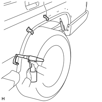
Install the bracket with 2 new rivets.
Using an air riveter or hand riveter with a nose piece, install the rear No. 2 wheel opening bracket front LH with 2 new rivets.
- HINT:
-
If the rivet cannot be cut, pull it once and cut it.
- NOTICE:
-
·
1.229,1.042 1.083,1.573 1.083,1.573 1.271,2.281 false 1.083,1.573 0.813,1.573 false 1.75,0.833 2.031,1.583 2.031,1.583 1.74,2.521 false 2.031,1.573 2.313,1.573 false 2.271,0.542 2.469,0.74 0.198,0.198 10 false *a 2.271,2.385 2.49,2.583 0.219,0.198 10 false *b 0.594,1.479 0.781,1.677 0.188,0.198 10 false *1 2.354,1.5 2.542,1.677 0.188,0.177 10 false *2
*1 Riveter *2 Mandrel *a INCORRECT *b CORRECT
Do not pry the rivet with the riveter, as this will cause damage to the riveter and mandrel.
·
2.325,0.536 2.513,0.713 0.189,0.177 10 *a 2.325,1.527 2.5,1.705 0.175,0.177 10 *a 2.434,2.73 2.634,2.907 0.2,0.177 10 *b 0.72,0.066 1.023,0.066 false 0.818,1.11 1.018,1.11 false 1.043,2.324 1.223,2.477 0.181,0.153 10 *1 1.043,1.044 1.223,1.196 0.181,0.153 10 *1 1.043,0.0040 1.223,0.157 0.181,0.153 10 *1 0.818,2.402 1.018,2.402 false*1 Riveter *a INCORRECT *b CORRECT
Confirm that the rivets are seated properly against the bracket.
·Do not tilt the riveter when installing the rivet to the bracket.
·Do not leave any space between the rivet head and bracket.
·
2.304,0.996 2.504,1.173 0.2,0.177 10 *a 2.408,2.434 2.62,2.612 0.211,0.177 10 *b 0.978,0.515 1.173,0.686 0.195,0.171 10 *1 0.735,0.603 0.941,0.603 false 0.973,2.023 1.182,2.194 0.209,0.171 10 *1 0.731,2.111 0.937,2.111 false*1 Riveter *a INCORRECT *b CORRECT
Do not leave any space between the bracket and door. Firmly hold together the 2 items while installing the rivet.
61783D 4.INSTALL REAR NO. 1 WHEEL OPENING EXTENSION PAD
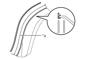
| *a | Installation position |
Install a new rear No. 1 wheel opening extension extension pad.
Remove the peeling paper from the face of a new rear No. 1 wheel opening extension pad.
Attach the rear No. 1 wheel opening extension pad as shown in the illustration.
61062C 5.INSTALL REAR NO. 1 WHEEL OPENING EXTENSION SUB-ASSEMBLY LH
Install the rear No. 1 wheel opening extension sub-assembly LH with the 2 nuts and bolt.
61693D 6.INSTALL REAR NO. 1 WHEEL OPENING BRACKET REAR LH
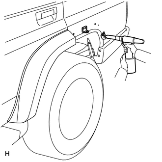
Install the 2 rear No. 1 wheel opening bracket rear LH with 4 new rivets.
Using an air riveter or hand riveter with a nose piece, install the rear No. 1 wheel opening bracket rear LH with 4 new rivets.
- HINT:
-
If the rivet cannot be cut, pull it once and cut it.
- NOTICE:
-
·
1.229,1.042 1.083,1.573 1.083,1.573 1.271,2.281 false 1.083,1.573 0.813,1.573 false 1.75,0.833 2.031,1.583 2.031,1.583 1.74,2.521 false 2.031,1.573 2.313,1.573 false 2.271,0.542 2.469,0.74 0.198,0.198 10 false *a 2.271,2.385 2.49,2.583 0.219,0.198 10 false *b 0.594,1.479 0.781,1.677 0.188,0.198 10 false *1 2.354,1.5 2.542,1.677 0.188,0.177 10 false *2
*1 Riveter *2 Mandrel *a INCORRECT *b CORRECT
Do not pry the rivet with the riveter, as this will cause damage to the riveter and mandrel.
·
2.325,0.536 2.513,0.713 0.189,0.177 10 *a 2.325,1.527 2.5,1.705 0.175,0.177 10 *a 2.434,2.73 2.634,2.907 0.2,0.177 10 *b 0.72,0.066 1.023,0.066 false 0.818,1.11 1.018,1.11 false 1.043,2.324 1.223,2.477 0.181,0.153 10 *1 1.043,1.044 1.223,1.196 0.181,0.153 10 *1 1.043,0.0040 1.223,0.157 0.181,0.153 10 *1 0.818,2.402 1.018,2.402 false*1 Riveter *a INCORRECT *b CORRECT
Confirm that the rivets are seated properly against the bracket.
·Do not tilt the riveter when installing the rivet to the bracket.
·Do not leave any space between the rivet head and bracket.
·
2.304,0.996 2.504,1.173 0.2,0.177 10 *a 2.408,2.434 2.62,2.612 0.211,0.177 10 *b 0.978,0.515 1.173,0.686 0.195,0.171 10 *1 0.735,0.603 0.941,0.603 false 0.973,2.023 1.182,2.194 0.209,0.171 10 *1 0.731,2.111 0.937,2.111 false*1 Riveter *a INCORRECT *b CORRECT
Do not leave any space between the bracket and rear fender panel. Firmly hold together the 2 items while installing the rivet.
53872C 7.INSTALL REAR NO. 8 WHEEL OPENING BRACKET REAR LH
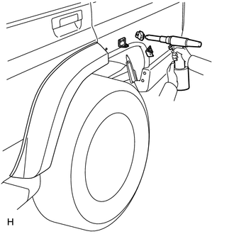
Install the rear No. 8 wheel opening bracket rear LH with 2 new rivets.
Using an air riveter or hand riveter with a nose piece, install the rear No. 8 wheel opening bracket rear LH with 2 new rivets.
- HINT:
-
If the rivet cannot be cut, pull it once and cut it.
- NOTICE:
-
·
1.229,1.042 1.083,1.573 1.083,1.573 1.271,2.281 false 1.083,1.573 0.813,1.573 false 1.75,0.833 2.031,1.583 2.031,1.583 1.74,2.521 false 2.031,1.573 2.313,1.573 false 2.271,0.542 2.469,0.74 0.198,0.198 10 false *a 2.271,2.385 2.49,2.583 0.219,0.198 10 false *b 0.594,1.479 0.781,1.677 0.188,0.198 10 false *1 2.354,1.5 2.542,1.677 0.188,0.177 10 false *2
*1 Riveter *2 Mandrel *a INCORRECT *b CORRECT
Do not pry the rivet with the riveter, as this will cause damage to the riveter and mandrel.
·
2.325,0.536 2.513,0.713 0.189,0.177 10 *a 2.325,1.527 2.5,1.705 0.175,0.177 10 *a 2.434,2.73 2.634,2.907 0.2,0.177 10 *b 0.72,0.066 1.023,0.066 false 0.818,1.11 1.018,1.11 false 1.043,2.324 1.223,2.477 0.181,0.153 10 *1 1.043,1.044 1.223,1.196 0.181,0.153 10 *1 1.043,0.0040 1.223,0.157 0.181,0.153 10 *1 0.818,2.402 1.018,2.402 false*1 Riveter *a INCORRECT *b CORRECT
Confirm that the rivets are seated properly against the bracket.
·Do not tilt the riveter when installing the rivet to the bracket.
·Do not leave any space between the rivet head and bracket.
·
2.304,0.996 2.504,1.173 0.2,0.177 10 *a 2.408,2.434 2.62,2.612 0.211,0.177 10 *b 0.978,0.515 1.173,0.686 0.195,0.171 10 *1 0.735,0.603 0.941,0.603 false 0.973,2.023 1.182,2.194 0.209,0.171 10 *1 0.731,2.111 0.937,2.111 false*1 Riveter *a INCORRECT *b CORRECT
Do not leave any space between the bracket and rear fender panel. Firmly hold together the 2 items while installing the rivet.
61695D 8.INSTALL REAR NO. 3 WHEEL OPENING BRACKET REAR LH
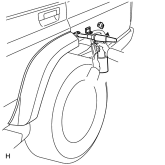
Install the rear No. 3 wheel opening bracket rear LH with 2 new rivets.
Using an air riveter or hand riveter with a nose piece, install the rear No. 3 wheel opening bracket rear LH with 2 new rivets.
- HINT:
-
If the rivet cannot be cut, pull it once and cut it.
- NOTICE:
-
·
1.229,1.042 1.083,1.573 1.083,1.573 1.271,2.281 false 1.083,1.573 0.813,1.573 false 1.75,0.833 2.031,1.583 2.031,1.583 1.74,2.521 false 2.031,1.573 2.313,1.573 false 2.271,0.542 2.469,0.74 0.198,0.198 10 false *a 2.271,2.385 2.49,2.583 0.219,0.198 10 false *b 0.594,1.479 0.781,1.677 0.188,0.198 10 false *1 2.354,1.5 2.542,1.677 0.188,0.177 10 false *2
*1 Riveter *2 Mandrel *a INCORRECT *b CORRECT
Do not pry the rivet with the riveter, as this will cause damage to the riveter and mandrel.
·
2.325,0.536 2.513,0.713 0.189,0.177 10 *a 2.325,1.527 2.5,1.705 0.175,0.177 10 *a 2.434,2.73 2.634,2.907 0.2,0.177 10 *b 0.72,0.066 1.023,0.066 false 0.818,1.11 1.018,1.11 false 1.043,2.324 1.223,2.477 0.181,0.153 10 *1 1.043,1.044 1.223,1.196 0.181,0.153 10 *1 1.043,0.0040 1.223,0.157 0.181,0.153 10 *1 0.818,2.402 1.018,2.402 false*1 Riveter *a INCORRECT *b CORRECT
Confirm that the rivets are seated properly against the bracket.
·Do not tilt the riveter when installing the rivet to the bracket.
·Do not leave any space between the rivet head and bracket.
·
2.304,0.996 2.504,1.173 0.2,0.177 10 *a 2.408,2.434 2.62,2.612 0.211,0.177 10 *b 0.978,0.515 1.173,0.686 0.195,0.171 10 *1 0.735,0.603 0.941,0.603 false 0.973,2.023 1.182,2.194 0.209,0.171 10 *1 0.731,2.111 0.937,2.111 false*1 Riveter *a INCORRECT *b CORRECT
Do not leave any space between the bracket and rear fender panel. Firmly hold together the 2 items while installing the rivet.
61785C 9.INSTALL REAR NO. 3 WHEEL OPENING EXTENSION PAD
Clean the rear No. 2 wheel opening extension sub-assembly LH surface.
Remove the double-sided tape from the rear No. 2 wheel opening extension sub-assembly LH.
Wipe off any tape adhesive residue with cleaner.
Install a new rear No. 3 wheel opening extension pad.
Remove the peeling paper from the face of the rear No. 3 wheel opening extension pad.
- HINT:
-
After removing the peeling paper, keep the exposed adhesive free from foreign matter.
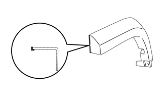
Install the rear No. 3 wheel opening extension pad as shown in the illustration.
- HINT:
-
Press the rear No. 3 wheel opening extension pad firmly to install it.
61785C 10.INSTALL REAR NO. 2 WHEEL OPENING EXTENSION PAD
Clean the rear No. 2 wheel opening extension sub-assembly LH surface.
Remove the double-sided tape from the rear No. 2 wheel opening extension sub-assembly LH.
Wipe off any tape adhesive residue with cleaner.
Install a new rear No. 2 wheel opening extension pad.
Remove the peeling paper from the face of the rear No. 2 wheel opening extension pad.
- HINT:
-
After removing the peeling paper, keep the exposed adhesive free from foreign matter.
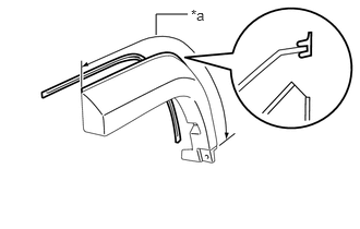
| *a | Installation position |
Install the rear No. 2 wheel opening extension pad as shown in the illustration.
- HINT:
-
Press the rear No. 2 wheel opening extension pad firmly to install it.
61064A 11.INSTALL REAR NO. 2 WHEEL OPENING EXTENSION SUB-ASSEMBLY LH
Install the rear No. 2 wheel opening extension sub-assembly LH with the 3 bolts.
76608 12.INSTALL REAR QUARTER PANEL MUDGUARD SUB-ASSEMBLY LH