WINCH WINCH UNIT DISASSEMBLY
PROCEDURE

 38600A 1.REMOVE WINCH MOTOR ASSEMBLY
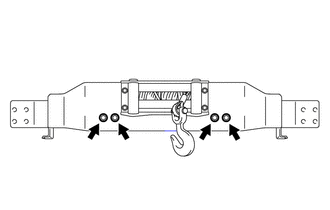
Remove the 4 bolts and member.
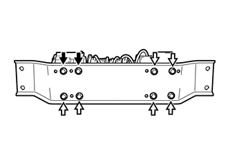

|
Bolt A |

|
Bolt B |
Remove the 2 bolts labeled A, 6 bolts labeled B and winch base.
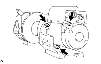
Remove the 3 bolts and winch motor assembly.
2.REMOVE WINCH BRAKE CASE SUB-ASSEMBLY
Remove the bolt and winch wire guide.
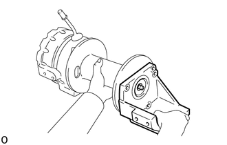
Remove the winch brake case sub-assembly
Remove the x-ring from the winch brake case sub-assembly.
3.REMOVE OIL SEAL
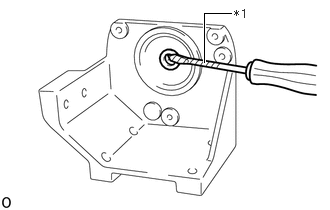
| *1 | Protective Tape |
Using a screwdriver, remove the oil seal.
- NOTICE:
-
Do not damage the winch brake case sub-assembly when removing the oil seal.
- HINT:
-
Tape the screwdriver tip before use.
38621B 4.REMOVE MAGNET SWITCH WINCH COVER
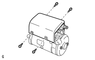
Remove the 4 screws and cover.
38600A 5.REMOVE WINCH MOTOR MAGNET SWITCH ASSEMBLY
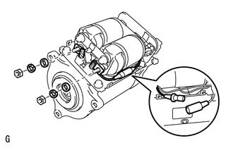
Disconnect the connector.
Remove the 2 nuts, 2 spring washers, 2 washers and wire harness.
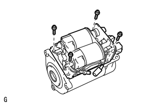
Remove the 4 bolts and magnet switch from the motor.
38618 6.REMOVE WINCH MOTOR COMMUTATOR END FRAME
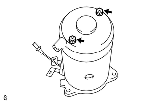
Remove the 2 bolts and commutator end frame.
38614A 7.REMOVE WINCH MOTOR O-RING
Remove the O-ring.
38613A 8.REMOVE WINCH MOTOR BRUSH
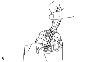
Using a screwdriver, pry the bush spring forward and pull the brush out of the holder.
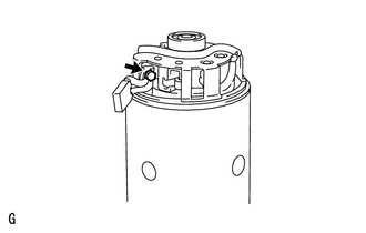
Remove the bolt and brush from the brush holder.
- HINT:
-
Use the same procedures to remove the 3 remaining brushes.
38604A 9.REMOVE WINCH MOTOR BRUSH HOLDER ASSEMBLY
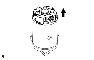
Remove the brush holder in the direction of the arrow shown in the illustration.
38601A 10.REMOVE WINCH MOTOR YOKE SUB-ASSEMBLY
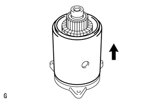
Remove the yoke in the direction of the arrow shown in the illustration.
38603A 11.REMOVE WINCH MOTOR ARMATURE SUB-ASSEMBLY
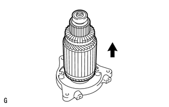
Remove the armature in the direction of the arrow shown in the illustration.
38603B 12.REMOVE NO. 1 WINCH MOTOR ARMATURE BEARING
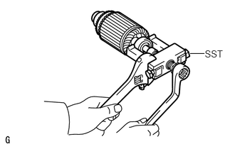
Using SST, remove the bearing.
- SST
-
09286-46011
38603C 13.REMOVE NO. 2 WINCH MOTOR ARMATURE BEARING
Using SST, remove the bearing.
- SST
-
09628-62011
38613B 14.REMOVE WINCH MOTOR BRUSH SPRING
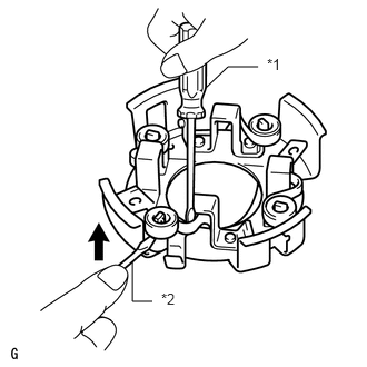
| *1 | Screwdriver A |
| *2 | Screwdriver B |
Insert a screwdriver, labeled A, as shown in the illustration and pry the spring forward, then move the spring in the direction of the arrow shown in the illustration with a screwdriver, labeled B, to remove it from the holder.