WINCH WINCH UNIT REASSEMBLY
PROCEDURE

 38613B 1.INSTALL WINCH MOTOR BRUSH SPRING
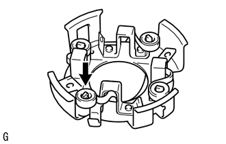
Install the brush spring as shown in the illustration.
38603B 2.INSTALL NO. 1 WINCH MOTOR ARMATURE BEARING
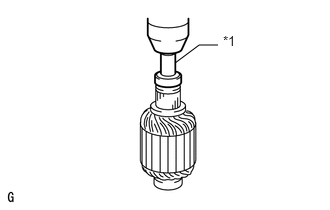
| *1 | 12 mm Socket Wrench |
Using a 12 mm socket wrench and press, press in a new bearing.
38603C 3.INSTALL NO. 2 WINCH MOTOR ARMATURE BEARING
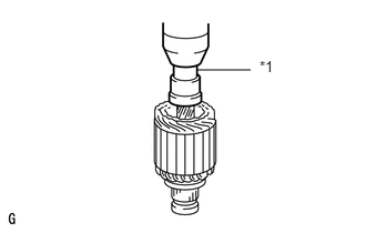
| *1 | 19 mm Socket Wrench |
Using a 19 mm socket wrench and press, press in a new bearing.
38603A 4.INSTALL WINCH MOTOR ARMATURE SUB-ASSEMBLY
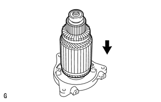
Apply high temperature grease to the inside of the end frame bushing.
Install the armature to the end frame.
38601A 5.INSTALL WINCH MOTOR YOKE SUB-ASSEMBLY
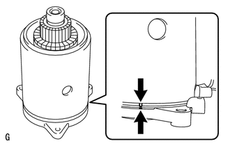
Align the alignment marks and install the yoke to the end frame.
38604A 6.INSTALL WINCH MOTOR BRUSH HOLDER ASSEMBLY
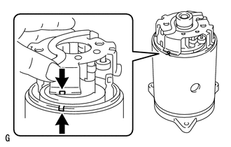
Align the alignment marks and install the brush holder to the yoke.
38613A 7.INSTALL WINCH MOTOR BRUSH
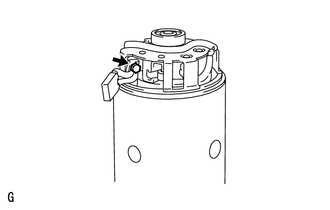
Install the brush with the bolt.
- Torque:
- 3.4 N*m (35 kgf*cm, 30 in.*lbf)
Using a screwdriver, pry the brush spring forward and insert the brush into the holder as shown in the illustration, then remove the screwdriver from the spring.
- HINT:
-
Use the same procedures to install the 3 remaining brushes.
38614A 8.INSTALL WINCH MOTOR O-RING
Install a new O-ring to the yoke.
38618 9.INSTALL WINCH MOTOR COMMUTATOR END FRAME
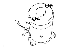
Install the end frame with the 2 bolts.
- Torque:
- 7.6 N*m (77 kgf*cm, 67 in.*lbf)
38600A 10.INSTALL WINCH MOTOR MAGNET SWITCH ASSEMBLY
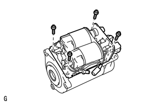
Install the switch to the motor with the 4 bolts.
- Torque:
- 4.9 N*m (50 kgf*cm, 43 in.*lbf)
Install the wire harness with the 2 washers, 2 spring washers and 2 nuts.
- Torque:
- 9.3 N*m (95 kgf*cm, 82 in.*lbf)
Connect the connector.
38621B 11.INSTALL MAGNET SWITCH WINCH COVER
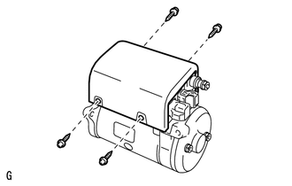
Install the cover with the 4 screws.
- Torque:
- 1.5 N*m (15 kgf*cm, 13 in.*lbf)
12.INSTALL OIL SEAL
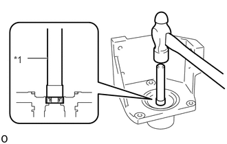
| *1 | SST |
Using SST, install a new oil seal.
- SST
-
09950-60010 09950-70010 (09951-00320, 09951-07150)
Apply MP grease to the new oil seal.
13.INSTALL WINCH BRAKE CASE SUB-ASSEMBLY
Apply MP grease to the new x-ring.
Install a new x-ring to the winch brake case sub-assembly.
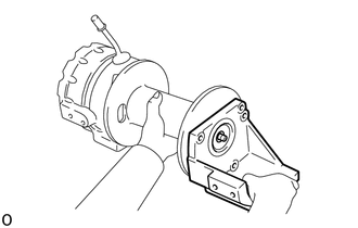
Install the winch brake case sub-assembly.
Install the winch wire guide with the bolt.
- Torque:
- 10 N*m (102 kgf*cm, 7 ft.*lbf)
38600A 14.INSTALL WINCH MOTOR ASSEMBLY
Install the winch motor assembly with the 3 bolts.
- Torque:
- 16 N*m (163 kgf*cm, 12 ft.*lbf)
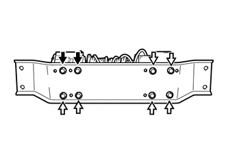

|
Bolt A |

|
Bolt B |
Install the winch base with the 8 bolts.
- Torque:
- for bolt A : 32 N*m (326 kgf*cm, 24 ft.*lbf)
- for bolt B : 59 N*m (602 kgf*cm, 44 ft.*lbf)
Install the member with the 4 bolts.
- Torque:
- 22 N*m (224 kgf*cm, 16 ft.*lbf)