DOOR / HATCH BACK DOOR(for LH Side) REASSEMBLY
CAUTION / NOTICE / HINT
- HINT:
-
·
A bolt without a torque specification is shown in the standard bolt chart.
Click hereGeneral>SPECIFICATIONS>STANDARD BOLT>SPECIFIED TORQUE FOR STANDARD BOLTS
PROCEDURE

 77196A 1.INSTALL AUXILIARY FUEL TANK CARRIER PAD (w/ Auxiliary Fuel Tank)
Install the auxiliary fuel carrier pad.
77107A 2.INSTALL AUXILIARY FUEL TANK CARRIER SUB-ASSEMBLY (w/ Auxiliary Fuel Tank)
Install the auxiliary fuel tank carrier sub-assembly with the 6 bolts and 6 nuts.
77197B 3.INSTALL AUXILIARY FUEL TANK CARRIER COVER (w/ Auxiliary Fuel Tank)
Install the auxiliary fuel tank carrier cover.
4.INSTALL HOLE PLUG (w/ Auxiliary Fuel Tank)
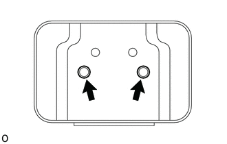
Install the 2 hole plugs.
5.INSTALL HOLE PLUG (w/ Auxiliary Fuel Tank)
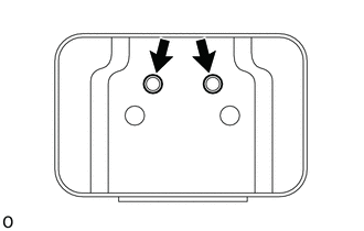
Install the 2 hole plugs.
75124A 6.INSTALL REAR LICENSE BRACKET (w/ Auxiliary Fuel Tank)
Install the nut to the rear license bracket.
77130 7.INSTALL AUXILIARY FUEL TANK BRACKET ASSEMBLY (w/ Auxiliary Fuel Tank)
Install the auxiliary fuel tank bracket assembly with the 4 bolts and 4 nuts.
75102 8.INSTALL REAR LICENSE PLATE BRACKET SUB-ASSEMBLY (w/ Auxiliary Fuel Tank)
Install the nut and rear license plate bracket sub-assembly.
67884C 9.INSTALL BACK DOOR LOWER WEATHERSTRIP LH (for Canvas Top)
Attach the 12 clips to install the back door lower weatherstrip LH.
67882C 10.INSTALL BACK DOOR NO. 2 WEATHERSTRIP (except Canvas Top)
Attach the 18 clips to install the back door weatherstrip.
68660 11.INSTALL BACK DOOR CHECK ASSEMBLY LH
Apply MP grease to the sliding areas of the back door check assembly LH.
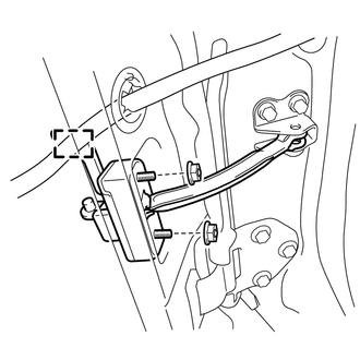
Install the door check to the door panel with the 2 nuts.
- Torque:
- 5.0 N*m (51 kgf*cm, 44 in.*lbf)
Connect the clamp.
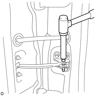
Using a brass bar and hammer, tap the door check pin into the body.
81270 12.INSTALL LICENSE PLATE LIGHT ASSEMBLY (w/ Auxiliary Fuel Tank)
81270 13.INSTALL LICENSE PLATE LIGHT ASSEMBLY
81690 14.INSTALL LICENSE PLATE LIGHT COVER SUB-ASSEMBLY (w/ Auxiliary Fuel Tank)
69350 15.INSTALL BACK DOOR LOCK ASSEMBLY
69212 16.INSTALL BACK DOOR OUTSIDE HANDLE LH
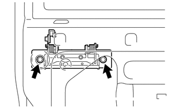
Install the 2 bolts to the back door outside handle assembly LH.
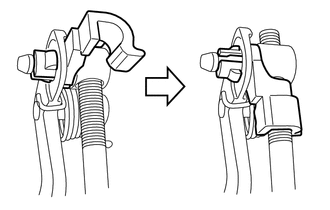
Attach the snap and connect the control link to the back door outside handle assembly LH as shown in the illustration.
69054 17.INSTALL BACK DOOR LOCK CYLINDER ASSEMBLY LH
Install the back door lock cylinder assembly LH.
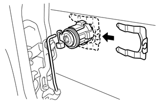
Install the plate.
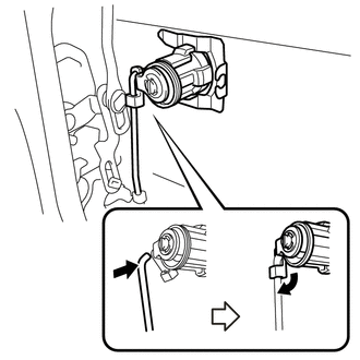
Attach the snap to the front door lock cylinder assembly LH as shown in the illustration.
69706A 18.INSTALL BACK DOOR LOCK REMOTE CONTROL ROD SUB-ASSEMBLY
Attach the 2 claws to install the holder.
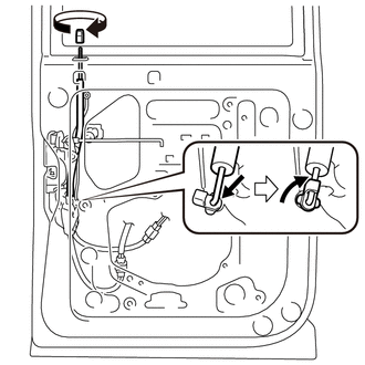
Install the back door lock remote control rod sub-assembly as shown in the illustration.
86161D 19.INSTALL NO. 1 SPEAKER MOUNTING BRACKET (w/ Back Door Speaker)
69759J 20.INSTALL DOOR LOCK LINK SILENCER
Clean the back door panel surface.
Remove the double-sided tape from the rear door panel surface.
Wipe off any tape adhesive residue with cleaner.
Install the door lock link silencer.
Remove the peeling paper from the face of the door lock link silencer.
- HINT:
-
After removing the peeling paper, keep the exposed adhesive free from foreign matter.
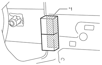
| *1 | Double-sided tape |
Install the door lock link silencer as shown in the illustration.
- HINT:
-
Press the door lock link silencer firmly to install it.
67848 21.INSTALL BACK DOOR SERVICE HOLE COVER LH
Apply new butyl tape to the back door panel LH.
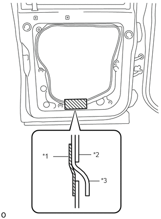
| *1 | Tape |
| *2 | Door Panel |
| *3 | Service Hole Cover |
Install the back door service hole cover LH.
- NOTICE:
-
·
When installing the service hole cover, pull out the links through the service hole cover.
·There should be no wrinkles or folds after attaching the service hole cover.
·After attaching the service hole cover, check the sealing quality.
Install the tape, as shown in the illustration.
68286 22.INSTALL BACK DOOR FRAME MOULDING LH (for Canvas Top)
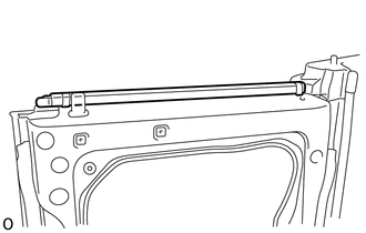
Install the back door frame moulding LH.
68608F 23.INSTALL BACK DOOR WINDOW FRAME SUB-ASSEMBLY LH (for Canvas Top)
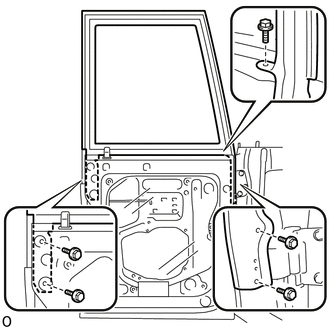
Install the 5 bolts to the back door window frame sub-assembly LH.
67882B 24.INSTALL BACK DOOR UPPER WEATHERSTRIP LH (for Canvas Top)
Install the 4 screws to the back door upper weatherstrip LH.
64790C 25.INSTALL BACK DOOR TRIM PANEL ASSEMBLY LH
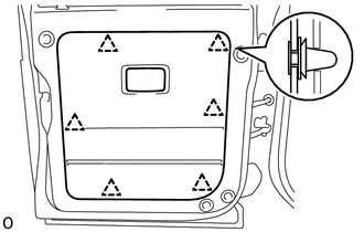
Attach the 6 clips to install the back door trim board sub-assembly LH.
69291 26.INSTALL BACK DOOR INSIDE HANDLE ASSEMBLY
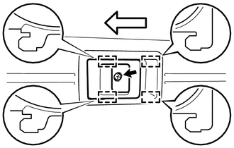
Connect the back door inside handle assembly to the control link and install the back door inside handle assembly.

|
Screw |

|
Rearward |
Attach the 4 guides in the direction indicated by the arrow in the illustration.
Install the screw and back door inside handle assembly.
86151 27.INSTALL SPEAKER BOX (w/ Back Door Speaker)
86160B 28.INSTALL REAR SPEAKER ASSEMBLY (w/ Back Door Speaker)
86264B 29.INSTALL REAR SPEAKER GRILLE (w/ Back Door Speaker)
86262B 30.INSTALL REAR SPEAKER COVER (w/ Back Door Speaker)
74811B 31.INSTALL DOOR PULL HANDLE
Install the 2 screws to the door pull handle.
32.INSTALL HOLE PLUG
Install the hole plug.
68852B 33.INSTALL BACK DOOR LOWER HINGE COVER
Install the back door lower hinge cover.
68851D 34.INSTALL BACK DOOR UPPER HINGE COVER
Install the back door upper hinge cover.
35.CHECK POWER DOOR LOCK CONTROL SYSTEM (w/ Power Door Lock)