HEATING / AIR CONDITIONING AIR CONDITIONING UNIT REASSEMBLY
PROCEDURE

 88539 1.INSTALL NO. 1 COOLER UNIT DRAIN HOSE
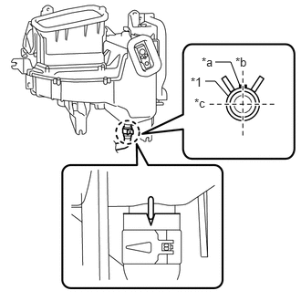
| *1 | Hose Clip |
| *a | No. 1 Cooler Unit Drain Hose Paint Mark for 1HZ: Pink for 1GR-FE: Yellow |
| *b | Front Side |
| *c | Left Side |
for LHD:
Align the cutout of the No. 1 cooler unit drain hose with the protrusion of the lower cooling case and install the No. 1 cooler unit drain hose.
Install the hose clip.
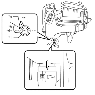
| *1 | Hose Clip |
| *a | No. 1 Cooler Unit Drain Hose Paint Mark for 1HZ, 1VD-FTV: Blue for 1GR-FE: Green |
| *b | 30° |
| *c | Front Side |
| *d | Left Side |
for RHD:
Align the cutout of the No. 1 cooler unit drain hose with the protrusion of the lower cooling case and install the No. 1 cooler unit drain hose.
Install the hose clip.
87138C 2.INSTALL BLOWER RESISTOR
Install the blower resistor with the 2 screws.
88625 3.INSTALL NO. 1 COOLER THERMISTOR
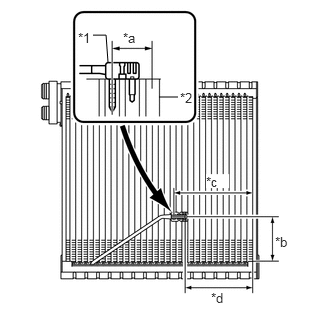
| *1 | Plastic Case |
| *2 | No. 1 Cooler Thermistor |
| *a | Range A |
| *b | 50.0 mm (1.9685 in.) (from tank upper surface) |
| *c | 89.6 mm (3.5276 in.) (from end face of No. 1 cooler evaporator sub-assembly) |
| *d | 76.2 mm (3.0000 in.) (from end face of No. 1 cooler evaporator) |
Install the No. 1 cooler thermistor as shown in the illustration.
- NOTICE:
-
·
Be sure to insert the thermistor only once because reinserting it into the same position will not allow it to be firmly secured.
·When reusing the evaporator, insert the thermistor one row next to the one that has been used previously (A in the illustration).
·After inserting the thermistor, do not apply excessive force to the wire.
·Directly insert the thermistor until the edge of the plastic case comes into contact with the evaporator.
88501 4.INSTALL NO. 1 COOLER EVAPORATOR SUB-ASSEMBLY
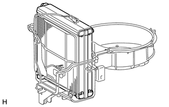
Install the No. 1 cooler evaporator sub-assembly to the lower blower case.
Install the air filter.
Install the upper cooling case.
Install the 10 screws and attach the clamp.
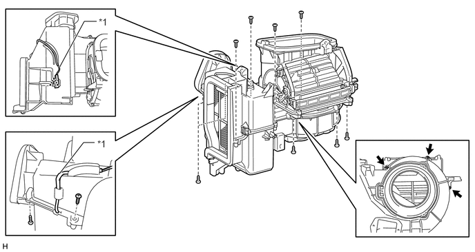
| *1 | No. 1 Cooler Thermistor Wire Harness | - | - |
88515 5.INSTALL COOLER EXPANSION VALVE
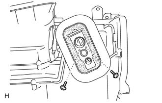
Sufficiently apply compressor oil to 2 new O-rings and the fitting surface of the hose joint.
- Compressor oil:
-
ND-OIL 8 or equivalent
Install the 2 O-rings to the No. 1 cooler evaporator sub-assembly.
Install the cooler expansion valve and packing to the No. 1 cooler evaporator sub-assembly.
Using a 4 mm hexagon wrench, install the 2 hexagon bolts.
- Torque:
- 3.5 N*m (36 kgf*cm, 31 in.*lbf)
87103B 6.INSTALL BLOWER WITH FAN MOTOR SUB-ASSEMBLY
Install the blower with fan motor sub-assembly with the 3 screws.
88568B 7.INSTALL AIR FILTER
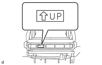
Align the "UP" marks as shown in the illustration and attach the 2 claws to install the air filter.