RM25T0E _56 Audio / Visual / Telematics _029922 AUDIO / VIDEO _0137914 AUDIO ANTENNA SWITCH G
AUDIO / VIDEO AUDIO ANTENNA SWITCH INSPECTION
PROCEDURE

 84760 1.INSPECT ANTENNA SWITCH ASSEMBLY
a.
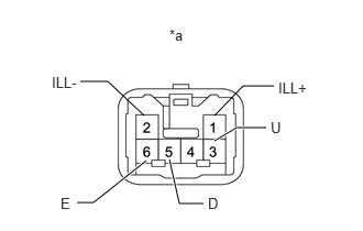
2.031,1.333 2.24,1.208 2.24,1.208 2.521,1.208 true 1.604,1.51 1.698,1.927 1.698,1.927 1.927,1.927 true 1.385,1.521 0.885,1.917 0.885,1.917 0.729,1.917 true 1.365,1.094 1.021,0.771 1.021,0.771 0.76,0.771 false 2.031,1.094 2.302,0.813 2.302,0.813 2.594,0.813 false 1.969,1.844 2.219,2.031 0.25,0.188 10 false D 2.563,1.125 3.063,1.313 0.5,0.188 10 false U 0.573,1.844 0.708,2.031 0.135,0.188 10 false E 1.604,0.25 1.917,0.448 0.313,0.198 10 false *a 2.635,0.75 3.25,0.948 0.615,0.198 10 false ILL+ 0.49,0.698 1.104,0.896 0.615,0.198 10 false ILL-
| *a | Component without harness connected (Antenna Switch Assembly) |
Measure the resistance according to the value(s) in the table below.
- Standard Resistance:
-
Tester Connection Switch Condition Specified Condition 3 (U) - 6 (E) Antenna up switch on Below 1 Ω 5 (D) - 6 (E) Antenna down switch on Below 1 Ω 3 (U) - 6 (E)
5 (D) - 6 (E)Antenna switch off 10 kΩ or higher
If the result is not as specified, replace the antenna switch assembly.
b.
Inspect the switch illumination
i.
Apply battery voltage to the vehicle sound switch connector and check that the switch illumination comes on.
- OK:
-
Measurement Condition Specified Condition Battery positive (+) → 1 (ILL+)
Battery negative (-) → 2 (ILL-)Switch illumination comes on
If the result is not as specified, replace the antenna switch assembly.