AXLE AND DIFFERENTIAL FRONT AXLE HUB INSTALLATION
CAUTION / NOTICE / HINT
- HINT:
-
·
Use the same procedure for the RH and LH sides.
·The procedure listed below is for the LH side.
PROCEDURE

 43512 1.INSTALL FRONT DISC
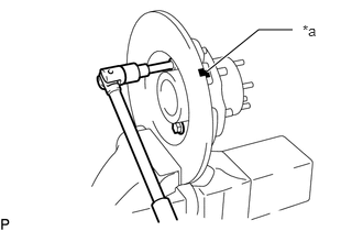
| *a | Matchmark |
Align the matchmarks on the front axle hub and front disc.
Install the 5 bolts to the front axle hub.
- Torque:
- 95 N*m (969 kgf*cm, 70 ft.*lbf)
2.INSTALL BEARING OUTER RACE
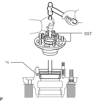
| *1 | Outside Bearing Outer Race |
Using SST and a hammer, install a new outside bearing outer race.
- SST
-
09950-60020 09950-70010 (09951-00720, 09951-07150)
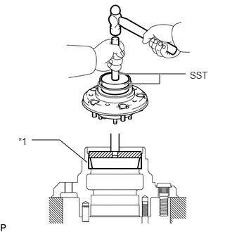
| *1 | Inside Bearing Outer Race |
Using SST and a hammer, install a new inside bearing outer race.
- SST
-
09950-60020 09950-70010 (09951-00810, 09951-07150)
3.PACK BEARING WITH MP GREASE
Place MP grease in the palm of your hand.
Pack grease into the bearing, continuing until the grease oozes out from the other side.
Do the same around the bearing circumference.
4.COAT INSIDE OF AXLE HUB WITH MP GREASE
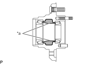
| *a | MP grease |
Coat the inside of the axle hub with MP grease.
5.INSTALL INNER BEARING
Place the inner bearing into the front axle hub.
43502F 6.INSTALL FRONT AXLE HUB OIL SEAL LH
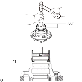
| *1 | Front Axle Hub Oil Seal |
Using SST, install a new front axle hub oil seal LH to the front axle hub.
- SST
-
09223-15020 09950-70010 (09951-07150)
Coat the seal lip with MP grease.
43502C 7.INSTALL FRONT AXLE HUB AND FRONT DISC
Place the front axle hub and front disc into the steering knuckle spindle sub-assembly.
Install the outer bearing.
Install the front axle hub claw washer.
8.ADJUST PRELOAD (w/ Dual Mode Automatic Locking Hub)
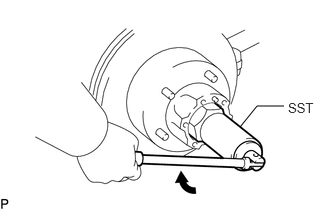
Using SST, tighten the front wheel adjusting nut.
- SST
-
09607-60020
- Torque:
- 58.8 N*m (600 kgf*cm, 43 ft.*lbf)
Turn the axle hub right and left 2 or 3 times.
Loosen the nut until it can be turned by hand.
Using SST, retighten the front wheel adjusting nut.
- SST
-
09607-60020
- Torque:
- 49 N*m (500 kgf*cm, 36 ft.*lbf)
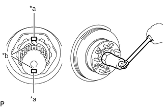
| *a | Spindle Key Grooves |
| *b | Adjusting Nut Grooves |
Tighten the front wheel adjusting nut so that the grooves of the front wheel adjusting nut are aligned with the key grooves of the spindle.
- Torque:
-
49 to 78.5 N*m (500 to 800 kgf*cm, 36 to 58 ft.*lbf)
- NOTICE:
-
Check that the bearing has no play.
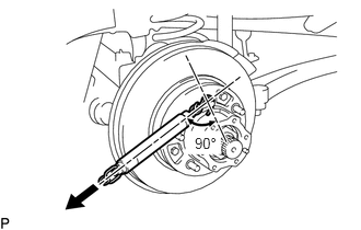
Using a spring tension gauge, measure the preload.
- Preload (at starting):
-
26 to 52 N (3 to 5 kgf, 5.8 to 11.7 lbf)
- HINT:
-
Make sure to check preload in the direction of rotation. If the preload is not within the specified range, adjust it again with the adjusting nut.
9.ADJUST PRELOAD (w/o Dual Mode Automatic Locking Hub)
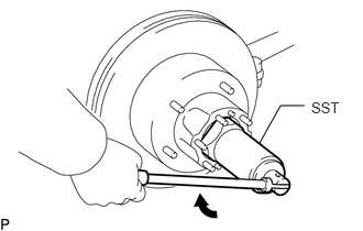
Using SST, tighten the front wheel adjusting nut.
- SST
-
09607-60020
- Torque:
- 58.8 N*m (600 kgf*cm, 43 ft.*lbf)
Turn the axle hub right and left 2 or 3 times.
Loosen the nut until it can be turned by hand.
Using SST, retighten the front wheel adjusting nut.
- SST
-
09607-60020
- Torque:
- 5.4 N*m (55 kgf*cm, 48 in.*lbf)
- NOTICE:
-
Check that the bearing has no play.
Using a spring tension gauge, measure the preload.
- Preload (at starting):
-
26 to 52 N (3 to 5 kgf, 5.8 to 11.7 lbf)
10.INSTALL BRAKE SET AND SPINDLE WASHER (w/ Dual Mode Automatic Locking Hub)
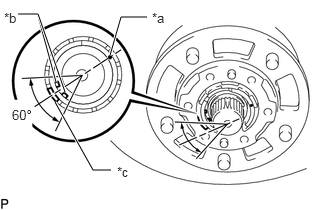
| *a | Brake Set Mark |
| *b | Brake Wire |
| *c | Brake Outer Raised Portion |
Check that the brake wire is within the 60° range of the brake outer raised portion on the opposite side to the brake set mark.
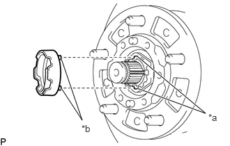
| *a | Spindle Key Grooves |
| *b | Brake Set Claws |
Align the claws of the brake set with the key grooves of the spindle and install the brake set.
Install the spindle washer and using a snap ring expander, install a new snap ring.
Install the bolt to the axle shaft.
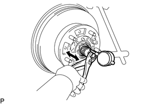
Using a dial indicator, check the backlash near the center of the axle shaft, while pulling the bolt with pliers.
- Maximum:
-
0.2 mm (0.008 in.)
- HINT:
-
If the backlash is not as specified, replace the snap ring.
- Snap ring thickness:
-
Mark Thickness B 2.75 to 2.80 mm (0.108 to 0.110 in.) C 2.55 to 2.60 mm (0.100 to 0.102 in.) D 2.35 to 2.40 mm (0.0925 to 0.0945 in.) E 2.15 to 2.20 mm (0.0846 to 0.0866 in.) F 1.95 to 2.00 mm (0.0768 to 0.0787 in.) G 1.75 to 1.80 mm (0.0689 to 0.0709 in.)
Remove the bolt from the front axle shaft.
43521D 11.INSTALL FRONT WHEEL ADJUSTING NUT LH (w/o Dual Mode Automatic Locking Hub)
Install a new front wheel adjusting lock washer and front wheel adjusting nut.
Using SST, tighten the front wheel adjusting nut.
- SST
-
09607-60020
- Torque:
- 63.7 N*m (650 kgf*cm, 47 ft.*lbf)
Check that front axle hub turns smoothly and that the bearing has no play.
Using a spring tension gauge, check the preload.
- Preload (at starting):
-
26 to 52 N (3 to 5 kgf, 5.8 to 11.7 lbf)
- HINT:
-
If the preload is not as specified, adjust it with the adjusting nut after removing the lock washer and lock nut.
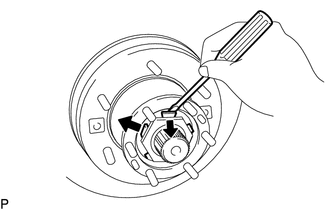
Secure the lock nut by bending one of the lock washer teeth inward and the other lock washer teeth outward.
43530 12.INSTALL DUAL MODE AUTOMATIC LOCKING HUB (w/ Dual Mode Automatic Locking Hub)
Install a new gasket to the front axle hub.
Check the knob of dual mode automatic locking hub in ''LOCK'' position.
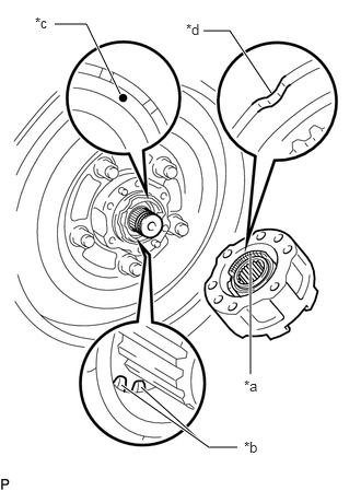
| *a | Claw of Release Plate |
| *b | Brake Wire |
| *c | Mark |
| *d | Align |
Align the marks on the brake set and notch on the locking hub.
- NOTICE:
-
·
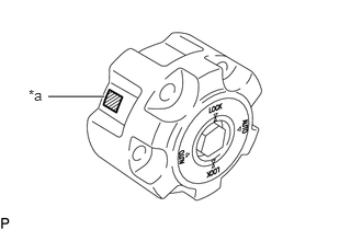 0.458,0.917 0.99,0.917 true 0.271,0.823 0.583,0.979 0.313,0.156 10 false *a
*a Identification Marks (No. 0 to 8)
Replace the rocking hub assembly for right and left at the same time, while matching the identification marks (No. 0 to 8) on both rocking hubs.
·Check that the brake wire of the brake set does not touch the claw on the release plate of the rocking hub.
Insert the gear drive of the locking hub into the axle shaft and push the locking hub into the axle hub.
- HINT:
-
While holding the rocking hub to the axle hub, ensure that there is no gap between the axle hub and rocking hub.
-
If there is a gap, the brake wire and claw of the release plate might touch. Check and repair it and confirm that there is no gap.
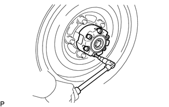
Using a 8 mm hexagon wrench, install new 6 hexagon bolts.
- Torque:
- 54.8 N*m (559 kgf*cm, 40 ft.*lbf)
43530 13.INSPECT FREE WHEEL HUB ASSEMBLY (w/ Free Wheel Hub)
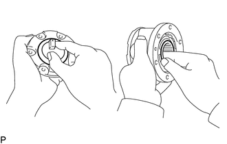
Check the handle moves smoothly.
Place the cover in the body and check that the inner hub turns smoothly.
43530 14.INSTALL FREE WHEEL HUB ASSEMBLY (w/ Free Wheel Hub)
Install a new gasket to the front axle hub.
Install the body with 6 cone washers, washers and new nuts.
- Torque:
- 32.6 N*m (332 kgf*cm, 24 ft.*lbf)
Select the snap ring which ensures the clearance between the tip of the body and the free wheel hub ring is less than 0.2 mm (0.008 in.).
- Snap ring thickness:
-
Mark Thickness B 2.75 to 2.80 mm (0.108 to 0.110 in.) C 2.55 to 2.60 mm (0.100 to 0.102 in.) D 2.35 to 2.40 mm (0.0925 to 0.0945 in.) E 2.15 to 2.20 mm (0.0846 to 0.0866 in.) F 1.95 to 2.00 mm (0.0768 to 0.0787 in.) G 1.75 to 1.80 mm (0.0689 to 0.0709 in.)
Using a snap ring expander, install a new free wheel hub ring LH.
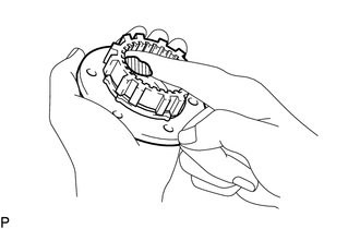
Apply MP grease to inner hub splines.
Set the control handle to FREE.
Place a new gasket in position on the body.
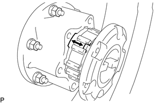
Install the cover to the body with the tabs of the pawl aligned with the non-toothed portions of the body.
Install the 6 bolts.
- Torque:
- 9.8 N*m (100 kgf*cm, 87 in.*lbf)
43421F 15.INSTALL FRONT AXLE OUTER SHAFT FLANGE LH (w/o Free Wheel Hub)
Place a new gasket in position on the front axle hub.
Apply MP grease to the inner flange spline.
Install the flange to the front axle hub.
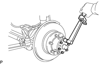
Install the 6 cone washers, plate washers and new nuts.
- Torque:
- 32.6 N*m (332 kgf*cm, 24 ft.*lbf)
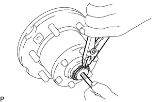
Install the bolt in the front axle shaft and pull it out.
Using a snap ring expander, install a new front drive shaft snap ring.
Remove the bolt.
43423 16.INSTALL FRONT AXLE OUTER SHAFT FLANGE CAP (w/o Free Wheel Hub)
Coat the inside of a new front axle outer shaft flange cap with MP grease.
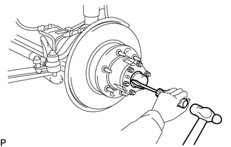
Install the front axle outer shaft flange cap to the front axle outer shaft flange.
17.INSTALL FRONT DISC BRAKE CYLINDER ASSEMBLY LH
Install the front disc brake cylinder assembly with the 2 bolts.
- Torque:
- 123 N*m (1254 kgf*cm, 91 ft.*lbf)
18.INSTALL FRONT SPEED SENSOR LH (w/ ABS)
Connect the front speed sensor with the nut.
- Torque:
- 8.5 N*m (87 kgf*cm, 75 in.*lbf)
- NOTICE:
-
·
Prevent foreign matter from adhering to the speed sensor.
·Be careful not to damage the speed sensor.
·Do not twist the sensor wire when installing the speed sensor.
19.INSTALL FRONT WHEEL