STEERING GEAR / LINKAGE STEERING GEAR INSPECTION
CAUTION / NOTICE / HINT
- NOTICE:
-
·
When using a vise, place aluminum plates between the part and vise.
·When using a vise, do not overtighten it.
- HINT:
-
·
Use the same procedure for RHD and LHD vehicles.
·The procedure listed below is for LHD vehicles.
PROCEDURE

 44120 1.INSPECT VALVE ASSEMBLY (WITH BALL NUT)
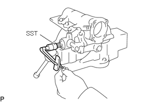
Using SST, check the preload of the valve assembly (with ball nut).
- SST
-
09616-00011
- Standard preload (at starting):
-
0.29 to 0.54 N*m (3 to 5 kgf*cm, 3 to 4 in.*lbf)
If preload is not correct, replace the valve assembly (with ball nut).
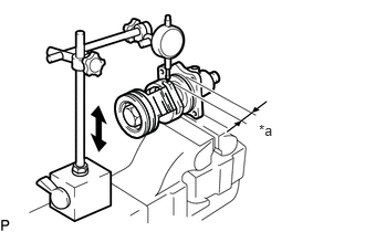
| *a | 30 mm (1.18 in.) |
Mount the valve assembly (with ball nut) in a vise.
Using a dial indicator, check the ball clearance. Move the worm gear up and down.
- Standard ball clearance:
-
0.005 to 0.015 mm (0.0002 to 0.0005 in.)
If clearance is excessive, replace the valve assembly (with ball nut).
44111 2.INSPECT CROSS SHAFT
Clamp the cross shaft in a vise.
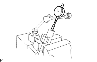
Using a dial indicator, measure the thrust clearance.
- Standard clearance:
-
0.03 to 0.05 mm (0.00119 to 0.00196 in.)
If thrust clearance is not correct, adjust the thrust clearance.