RM25T0E _58 Vehicle Interior _029931 SEAT BELT _0138409 SEAT BELT WARNING SYSTEM U
SEAT BELT SEAT BELT WARNING SYSTEM TERMINALS OF ECU
CHECK COMBINATION METER ASSEMBLY
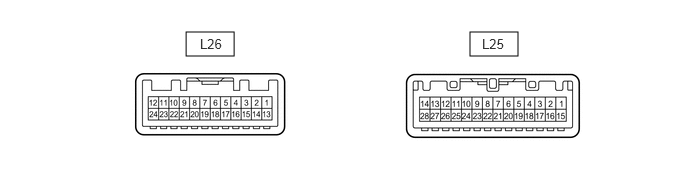
1.938,0.333 2.438,0.583 0.5,0.25 4.896,0.333 5.396,0.583 0.5,0.25 2.083,0.375 2.542,0.573 0.458,0.198 10 false L26 5.021,0.375 5.479,0.573 0.458,0.198 10 false L25
a.
Disconnect the L25 combination meter assembly connector.
b.
Measure the resistance and voltage according to the value(s) in the table below.
| Terminal No. (Symbol) | Wiring Color | Terminal Description | Condition | Specified Condition |
|---|---|---|---|---|
| L25-15 (ES) - Body ground | BR - Body ground | Ground | Always | Below 1 Ω |
| L25-26 (B) - Body ground | R - Body ground | Battery power supply | Always | 11 to 14 V |
| L25-28 (B) - Body ground | B-Y - Body ground | IG power supply | Ignition switch ON | 11 to 14 V |
| Ignition switch off | Below 1 V |
c.
Reconnect the L25 combination meter assembly connector.
d.
Measure the voltage and check for pulses according to the value(s) in the table below.
| Terminal No. (Symbol) | Wiring Color | Terminal Description | Condition | Specified Condition |
|---|---|---|---|---|
| L25-9 (SI) - Body ground | G-R - Body ground | Speed signal (input) | Ignition switch ON, wheel turned slowly | Pulse generation |
| L25-21 (SW) - Body ground | P - Body ground | Seat belt warning light signal | Ignition switch ON, driver side seat buckle switch is fastened | Below 1 V |
| Ignition switch ON, driver side seat buckle switch is unfastened | Alternating between 11 to 14 V and below 1 V |