BRAKE (REAR) REAR BRAKE(for Rear Drum Brake) REASSEMBLY
CAUTION / NOTICE / HINT
- HINT:
-
·
Use the same procedure for the RH and LH sides.
·The procedure listed below is for the LH side.
PROCEDURE

 47625A 1.INSTALL PARKING BRAKE BELL CRANK LH
Apply lithium soap base glycol grease to the bell crank boot.
Install the bell crank boot to the parking brake bell crank LH.
Install the parking brake bell crank LH to the bell crank bracket.
Apply lithium soap base glycol grease to the pin.
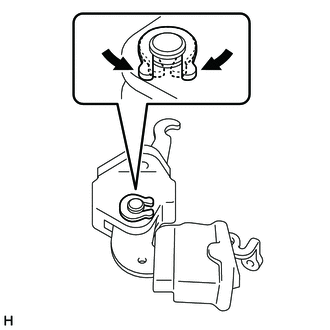
Install the pin with a new C-washer.
Install the parking brake bell crank LH with the 2 bolts.
- Torque:
- 12.5 N*m (127 kgf*cm, 9 ft.*lbf)
Connect the No. 1 parking brake cable assembly to the parking brake bell crank LH with the pin and clip.
w/o ABS:
Install the 2 tension springs from the parking brake bell crank LH.
w/ ABS:
Install the tension spring from the parking brake bell crank LH.
2.INSTALL REAR WHEEL BRAKE CYLINDER CUP
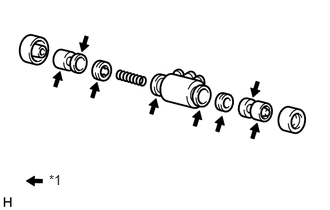
| *1 | Lithium soap base glycol grease |
Apply a light coat of lithium soap base glycol grease to 2 new rear wheel brake cylinder cups and 2 pistons.
Install the 2 rear wheel brake cylinder cups to the 2 pistons.
Install the compression spring and 2 pistons to the rear wheel brake cylinder assembly LH.
Install 2 new cylinder boots to the rear wheel brake cylinder assembly LH.
47547R 3.TEMPORARILY INSTALL REAR BRAKE DRUM BLEEDER PLUG
Temporarily install the bleeder plug to the rear wheel brake cylinder assembly LH.
- HINT:
-
The bleeder plug will be tightened to a torque specification in the Bleed Brake Line procedures.
31478C 4.INSTALL REAR DISC BRAKE BLEEDER PLUG CAP
47570 5.INSTALL REAR WHEEL BRAKE CYLINDER ASSEMBLY LH
Install the rear wheel brake cylinder assembly LH with the 2 bolts.
- Torque:
- 9.5 N*m (97 kgf*cm, 84 in.*lbf)
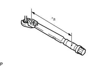
| *a | Torque Wrench Fulcrum Length |
Using a union nut wrench, connect the brake tube.
- Torque:
- Specified tightening torque : 15.2 N*m (155 kgf*cm, 11 ft.*lbf)
- HINT:
-
·
Calculate the torque wrench reading when changing the fulcrum length of the torque wrench.
Click hereGeneral>INTRODUCTION>REPAIR INSTRUCTION>PRECAUTION
·When using a union nut wrench (fulcrum length of 22 mm (0.8661 in.)) + torque wrench (fulcrum length of 162 mm (6.3779 in.)): 13.4 N*m (137 kgf*cm, 10 ft.*lbf)
47619 6.INSTALL PARKING BRAKE WIRE LH
Install the parking brake wire LH to the parking brake bell crank LH.
7.APPLY HIGH-TEMPERATURE GREASE
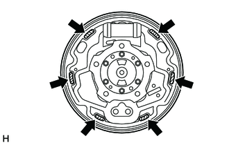

|
High-temperature grease |
Apply high-temperature grease to the surface of the backing plate which contacts the shoe.
47612A 8.INSTALL PARKING BRAKE SHOE LEVER LH (w/o ABS)
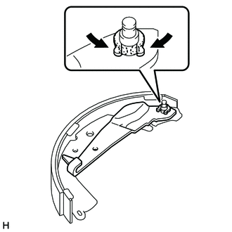
Install the parking brake shoe lever LH with a new C-washer.
47664 9.INSTALL REAR BRAKE AUTOMATIC ADJUST LEVER (w/o ABS)
Install the rear brake automatic adjust lever with a new E-ring.
47430G 10.INSTALL REAR BRAKE AUTOMATIC ADJUST LEVER TENSION SPRING (w/o ABS)
Using SST, install the rear brake automatic adjust lever tension spring.
- SST
-
09703-30011
47062 11.INSTALL PARKING BRAKE SHOE STRUT SET LH (w/o ABS)

|
High-temperature grease |
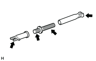
Disassembly the parking brake shoe strut set LH. Apply high temperature grease to the areas indicated by the arrows in the illustration. Then reassemble the parking brake shoe strut set LH.
Install the return spring to the parking brake shoe strut set LH.
Install the parking brake strut set LH to the front brake shoe.
12.INSTALL FRONT BRAKE SHOE (w/o ABS)
Using pliers, connect the parking brake cable to the parking brake shoe lever LH.
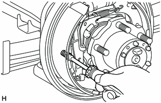
Install the front brake shoe, shoe hold down spring pin, shoe hold down spring and shoe hold down spring cup.
13.INSTALL REAR BRAKE SHOE (w/o ABS)
Connect the shoe tension spring to the front brake shoe and rear brake shoe.
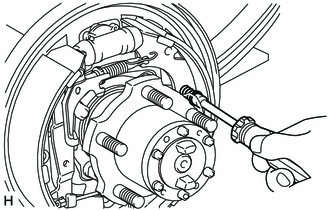
Install the rear brake shoe, shoe hold down spring pin, shoe hold down spring and shoe hold down spring cup.
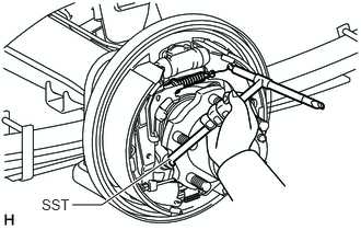
Using SST install the return spring to the rear brake shoe.
- SST
-
09703-30011
47612A 14.INSTALL PARKING BRAKE SHOE LEVER LH (w/ ABS)
|
|
High-temperature grease |
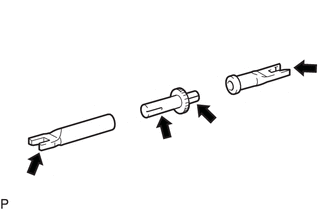
Disassembly the parking brake shoe strut set LH. Apply high temperature grease to the areas indicated by the arrows in the illustration. Then reassemble the parking brake shoe strut set LH.
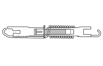
Assemble the parking brake shoe strut set LH as shown in the illustration.
Install the parking brake shoe lever LH with a new C-washer.
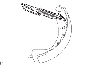
Install the parking brake shoe strut set LH to the front brake shoe.
47664 15.INSTALL REAR BRAKE AUTOMATIC ADJUST LEVER (w/ ABS)
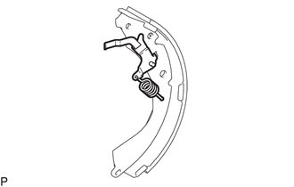
Install the rear brake automatic adjust lever and rear brake automatic adjust lever tension spring to the rear brake shoe.
47619 16.CONNECT PARKING BRAKE WIRE LH (w/ ABS)
Using needle-nose pliers, connect the parking breke wire LH to the rear brake parking brake shoe lever.
04943A 17.INSTALL REAR BRAKE STRUT KIT (w/ ABS)
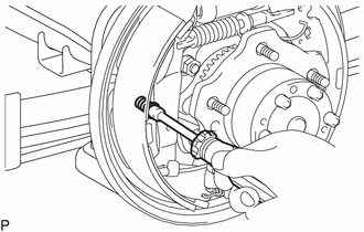
Install the front brake shoe, shoe hold down spring pin, shoe hold down spring and shoe hold down spring cup.
Install the shoe tension spring.
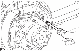
Install the rear brake shoe, shoe hold down spring pin, shoe hold down spring and shoe hold down spring cup.
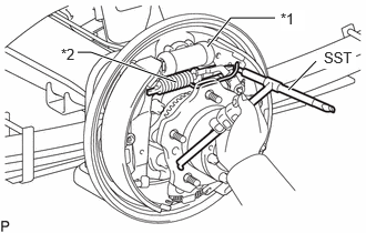
| *1 | Wheel Cylinder Boot |
| *2 | Return Spring |
Using SST, install the return spring to the rear brake shoe.
- SST
-
09921-00011
- NOTICE:
-
Do not damage the wheel cylinder boot.
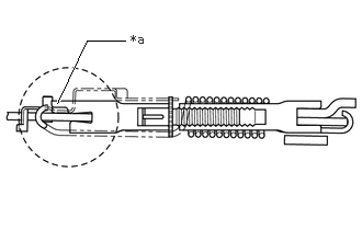
| *a | Ends of the Rear Brake Strut Kit |
Check that the parking brake shoe strut set LH is installed properly as shown in the illustration.
- NOTICE:
-
Make sure that the ends of the parking brake shoe strut set LH are facing the correct direction by checking the difference in length of the ends.
18.INSTALL REAR SPEED SENSOR LH (w/ ABS)
42403 19.CHECK REAR BRAKE DRUM INSTALLATION
w/o ABS:
Check that each part is installed properly.
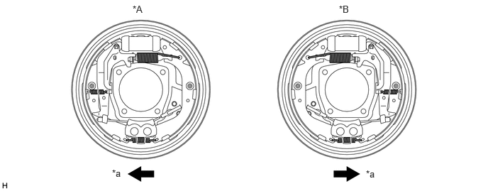
| *A | LH Side | *B | RH side |
| *a | Front | - | - |
w/ ABS:
Check that each part is installed properly.
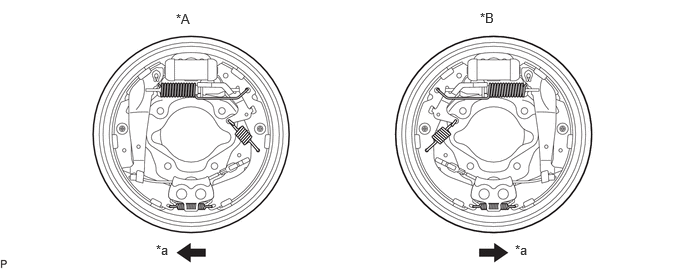
| *A | LH Side | *B | RH side |
| *a | Front | - | - |
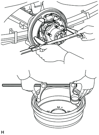
Measure the brake drum inner diameter and the diameter of the brake shoes. Check that the difference between the diameters is equal to the specified shoe clearance.
- Standard shoe clearance:
-
0.6 mm (0.0236 in.)
- NOTICE:
-
There should be no oil or grease on the contact surfaces of the shoe lining and drum.
47625A 20.ADJUST PARKING BRAKE BELL CRANK LH
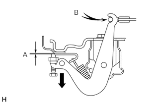
|
|
Pull |
Lightly pull the parking brake bell crank LH in direction until there is no slack at part B.
Adjust the gap between the stopper bolt and the backing plate.
- Gap A:
-
0.4 to 0.8 mm (0.0157 to 0.0315 in.)
Lock the adjust bolt with the lock nut.
- Torque:
- 5.0 N*m (51 kgf*cm, 44 in.*lbf)