LIGHTING (EXT) FRONT TURN SIGNAL LIGHT BULB REPLACEMENT
CAUTION / NOTICE / HINT
- HINT:
-
·
Use the same procedure for the RH and LH sides.
·The procedure listed below is for the LH side.
PROCEDURE

 81515B 1.REMOVE FRONT TURN SIGNAL LIGHT SOCKET
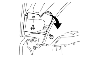
Remove the 2 clips and disconnect the fender apron splash plate LH.
Disconnect the connector.
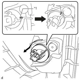
| *1 | Matchmark |
| *2 | Unlock Position Mark |
Turn the front turn signal light socket counterclockwise until the matchmark is aligned with the unlock position mark to remove the front turn signal light socket from the headlight unit assembly LH.
81510C 2.REMOVE FRONT TURN SIGNAL LIGHT BULB
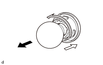

|
Push |

|
Counterclockwise |
Push the front turn signal light bulb in the direction indicated by the white arrow shown in the illustration, turn the bulb counterclockwise, and then remove the bulb from the front turn signal light socket.
81510C 3.INSTALL FRONT TURN SIGNAL LIGHT BULB
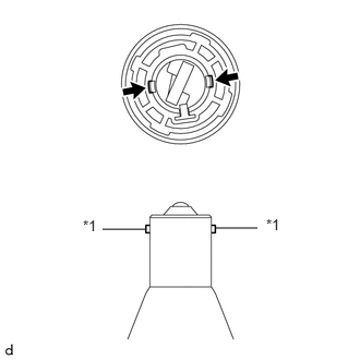
| *1 | Protrusion |

|
Cutout |
Align the 2 protrusions on the front turn signal light bulb with the 2 cutouts of the bulb socket and insert the bulb.
|
|
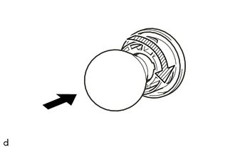
Clockwise |
While pushing the front turn signal light bulb, turn the bulb clockwise to install the bulb.
81515B 4.INSTALL FRONT TURN SIGNAL LIGHT SOCKET
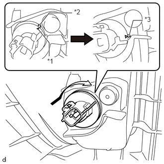
| *1 | Matchmark |
| *2 | Unlock Position Mark |
| *3 | Lock Position Mark |
Align the matchmark of the front turn signal light socket to the unlock position mark, and then rotate the front turn signal light socket clockwise until the lock position mark to install the front turn signal light socket to the headlight unit assembly LH.
Connect the connector.
Connect the fender apron splash plate LH with the 2 clips.