RM25T0E _59 Vehicle Exterior _029940 LIGHTING (EXT) _0138189 STOP LIGHT SWITCH A
LIGHTING (EXT) STOP LIGHT SWITCH INSTALLATION
CAUTION / NOTICE / HINT
- HINT:
-
·
Use the same procedure for RHD and LHD vehicles.
·The procedure listed below is for LHD vehicles.
PROCEDURE

 84340 1.INSTALL STOP LIGHT SWITCH ASSEMBLY
a.
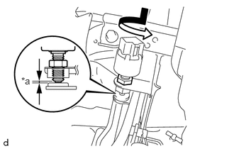
0.313,1.104 0.625,1.26 0.313,0.156 10 false *a
| *a | Protrusion Amount Measurement Area |
Turn the stop light switch assembly in the clockwise direction until it reaches the standard shaft protrusion amount and temporarily install it.
- Standard:
-
0.5 to 2.4 mm (0.0197 to 0.0945 in.)
- NOTICE:
-
Do not depress the brake pedal.
b.
Tighten the lock nut.
- Torque:
- 16.7 N*m (170 kgf*cm, 12 ft.*lbf)
c.
Connect the connector.
55480D 2.INSTALL LOWER INSTRUMENT PANEL FINISH PANEL ASSEMBLY
3.INSPECT STOP LIGHT
a.
Depress the brake pedal and check that the brake light illuminates.