BRAKE SYSTEM (OTHER) LOAD SENSING PROPORTIONING VALVE REASSEMBLY
PROCEDURE

 47936 1.TEMPORARILY INSTALL NO. 2 LOAD SENSING SPRING SHACKLE
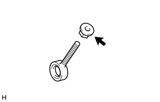
Temporarily install the adjusting nut to the No. 2 load sensing spring shackle.
47935 2.TEMPORARILY INSTALL NO. 1 LOAD SENSING SPRING SHACKLE
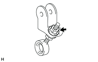
Connect the No. 1 load sensing spring shackle to the No. 2 load sensing spring shackle.
Temporarily install the lock nut to the No. 1 load sensing spring shackle.
- HINT:
-
The adjusting nut and lock nut will be tightened to a torque specification in the "ADJUST LOAD SENSING PROPORTIONING VALVE ASSEMBLY" procedure.
47920 3.INSTALL LOAD SENSING SPRING ASSEMBLY
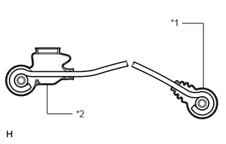
| *1 | Spring Boot |
| *2 | Valve Boot |
Install the valve boot and spring boot to the spring as shown in the illustration.
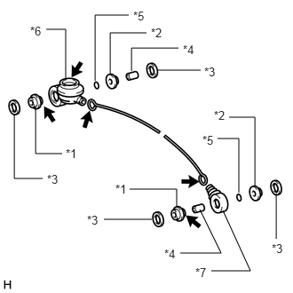
| *1 | No. 1 Load Sensing Spring Bush |
| *2 | No. 2 Load Sensing Spring Bush |
| *3 | Plate Washer |
| *4 | Load Sensing Spring Collar |
| *5 | Load Sensing Spring Washer |
| *6 | Load Sensing Valve Boot |
| *7 | Load Sensing Spring Boot |

|
Lithium soap base glycol grease |
Apply lithium soap base glycol grease to the lip part of the load sensing valve boot and contact surface of the load sensing spring and No. 1 load sensing spring bush.
Install the 2 load sensing spring collars, 2 load sensing spring washers, 2 No. 1 load sensing spring bushes, 2 No. 2 load sensing spring bushes and 4 plate washers to the load sensing spring.
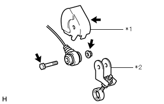
| *1 | Load Sensing Spring Shackle Heat Insulator |
| *2 | No. 1 Load Sensing Spring Shackle |
Connect the load sensing spring to the No. 1 load sensing spring shackle, and then install the load sensing spring shackle heat insulator with the bolt and nut.
- Torque:
- 18 N*m (184 kgf*cm, 13 ft.*lbf)
- NOTICE:
-
Insert the bolt as shown in the illustration.
47933 4.INSTALL NO. 1 LOAD SENSING SHACKLE BRACKET
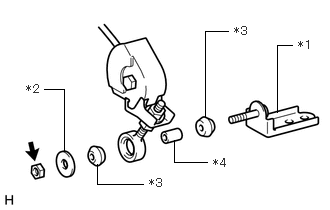
| *1 | No. 1 Load Sensing Shackle Bracket |
| *2 | Plate Washer |
| *3 | Load Sensing Spring Shackle Bush |
| *4 | Load Sensing Spring Shackle Collar |
Install the load sensing spring shackle collar, 2 load sensing spring shackle bushes, plate washer and No. 1 load sensing shackle bracket to the No. 2 load sensing spring shackle with the nut.
- Torque:
- 12.5 N*m (127 kgf*cm, 9 ft.*lbf)
47910 5.INSTALL LOAD SENSING PROPORTIONING VALVE
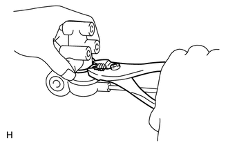
Using pliers, install the load sensing proportioning valve with the clip.
47931 6.INSTALL LOAD SENSING VALVE BRACKET
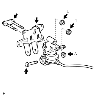
Install the bracket A to the valve with the nut B and bolt C.
- Torque:
- 18 N*m (184 kgf*cm, 13 ft.*lbf)
- NOTICE:
-
Insert the bolt as shown in the illustration.
Install the set plate D to the valve with the 2 nuts E.
- Torque:
- 12.5 N*m (127 kgf*cm, 9 ft.*lbf)