INTERIOR PANELS / TRIM INSTRUMENT PANEL SAFETY PAD REASSEMBLY
CAUTION / NOTICE / HINT
- HINT:
-
·
Use the same procedure for RHD and LHD vehicles.
·The procedure listed below is for LHD vehicles.
·A bolt without a torque specification is shown in the standard bolt chart.
Click hereGeneral>SPECIFICATIONS>STANDARD BOLT>SPECIFIED TORQUE FOR STANDARD BOLTS
PROCEDURE

 55448A 1.INSTALL NO. 1 INSTRUMENT PANEL FINISH CUSHION
- HINT:
-
Use the same procedure for both No. 1 instrument panel finish cushions.
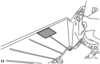
Remove the peeling paper from a new No. 1 instrument panel finish cushion and press firmly to install the No. 1 instrument panel finish cushion in the position shown in the illustration.
86101 2.INSTALL ANTENNA CORD SUB-ASSEMBLY
Attach the clamps to install the antenna cord sub-assembly.
55660 3.INSTALL NO. 2 INSTRUMENT PANEL REGISTER ASSEMBLY
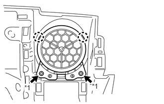
| *1 | Bolt <B> |
Attach the 2 claws to install the No. 2 instrument panel register assembly.
Install the 2 bolts <B>.
55650 4.INSTALL NO. 1 INSTRUMENT PANEL REGISTER ASSEMBLY
- HINT:
-
Use the same procedure described for the No. 2 instrument panel register assembly.
55680A 5.INSTALL NO. 4 INSTRUMENT PANEL REGISTER ASSEMBLY (w/ Air Conditioning System)
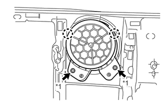
| *1 | Bolt <B> |
Attach the 2 claws to install the No. 4 instrument panel register assembly.
Install the 2 bolts <B>.
55670 6.INSTALL NO. 3 INSTRUMENT PANEL REGISTER ASSEMBLY (w/ Air Conditioning System)
- HINT:
-
Use the same procedure described for the No. 4 instrument panel register assembly.
7.INSTALL NO. 2 INSTRUMENT PANEL REGISTER OPENING COVER (w/o Air Conditioning System)
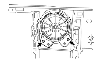
| *1 | Bolt <B> |
Attach the 2 claws to install the No. 2 instrument panel register opening cover.
Install the 2 bolts <B>.
8.INSTALL NO. 1 INSTRUMENT PANEL REGISTER OPENING COVER (w/o Air Conditioning System)
- HINT:
-
Use the same procedure described for the No. 2 instrument panel register opening cover.
55846B 9.INSTALL NO. 4 HEATER TO REGISTER DUCT
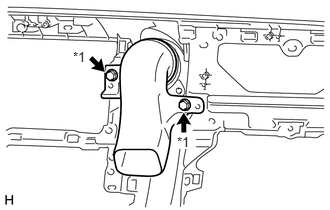
| *1 | Bolt <B> |
Install the No. 4 heater to register duct with the 2 screws <B>.
55845A 10.INSTALL NO. 3 HEATER TO REGISTER DUCT
- HINT:
-
Use the same procedure described for the No. 4 heater to register duct.
55950G 11.INSTALL DEFROSTER NOZZLE ASSEMBLY
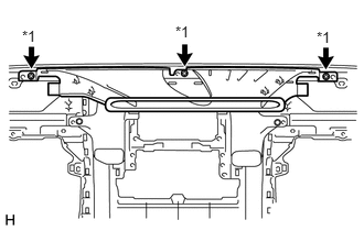
| *1 | Bolt <B> |
Install the defroster nozzle assembly with the 3 screws <B>.
55089 12.INSTALL NO. 6 HEATER TO REGISTER DUCT SUB-ASSEMBLY
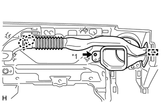
| *1 | Bolt <B> |
Attach the 2 claws and guide to install the No. 6 heater to register duct sub-assembly.
55084E 13.INSTALL NO. 1 HEATER TO REGISTER DUCT SUB-ASSEMBLY
- HINT:
-
Use the same procedure described for the No. 6 heater to register duct sub-assembly.
55312C 14.INSTALL INSTRUMENT RETAINER PLATE
Install the instrument retainer plate with the 2 bolts <A> and 7 bolts <B>.
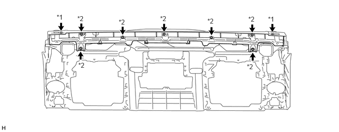
| *1 | Bolt <A> | *2 | Bolt <B> |