RM25T0E _58 Vehicle Interior _029927 METER / GAUGE / DISPLAY _0140599 CLOCK SYSTEM U
METER / GAUGE / DISPLAY CLOCK SYSTEM TERMINALS OF ECU
CHECK CLOCK ASSEMBLY

3.354,0.479 3.792,0.729 0.438,0.25 3.49,0.51 3.781,0.698 0.292,0.188 10 false L9
a.
Measure the voltage, resistance and waveform according to the value(s) in the table below.
| Terminal No. | Wiring Color | Terminal Description | Condition | Specified Condition |
|---|---|---|---|---|
|
*: for Multi Clock |
||||
| L9-1 (B) - Body ground | P - Body ground | +B power supply | Always | 11 to 14 V |
| L9-2 (ACC) - Body ground | GR - Body ground | ACC power supply | Ignition switch ACC | 11 to 14 V |
| Ignition switch off | Below 1 V | |||
| L9-3 (ILL+) - Body ground | G - Body ground | Illumination light signal | Light control switch TAIL | 11 to 14 V |
| Ignition switch off | Below 1 V | |||
| L9-4 (IG) - Body ground* | L - Body ground | IG power supply | Ignition switch ON | 11 to 14 V |
| Ignition switch off | Below 1 V | |||
| L9-5 (SPD) - Body ground* | G - Body ground | Speed signal | Driving at approximately 20 km/h (12 mph) | Pulse generation (See waveform) |
| L9-6 (TES+) - L9-7 (TES-)* | B-L - Y-B | Ambient temperature sensor signal | Ignition switch ON | 4.4 to 5.6 V |
| L9-8 (GND) - Body ground | W-B - Body ground | Body ground | Always | Below 1 Ω |
| Terminal No. | Wiring Color | Terminal Description | Condition | Specified Condition |
|---|---|---|---|---|
| L9-1 (B) - Body ground | P - Body ground | +B power supply | Always | 20 to 28 V |
| L9-2 (ACC) - Body ground | GR - Body ground | ACC power supply | Ignition switch ACC | 20 to 28 V |
| Ignition switch off | Below 1 V | |||
| L9-3 (ILL+) - Body ground | G - Body ground | Illumination light signal | Light control switch TAIL | 20 to 28 V |
| Ignition switch off | Below 1 V | |||
| L9-8 (GND) - Body ground | W-B - Body ground | Body ground | Always | Below 1 Ω |
i.
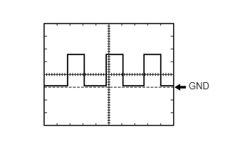
2.759,1.171 3.096,1.327 0.337,0.156 10 GND
Using an oscilloscope, check waveform.
| Item | Condition |
|---|---|
| Tester Connection | L9-5 (SPD) - Body ground |
| Tool Setting | 5 V/DIV., 20 msec./DIV. |
| Condition | Driving at approximately 20 km/h (12 mph) |
- HINT:
-
As the vehicle speed increases, the wavelength shortens.