BF1B TRANSFER / 4WD / AWD TRANSFER ASSEMBLY DISASSEMBLY
CAUTION / NOTICE / HINT
- NOTICE:
-
·
When using a vise, place aluminum plates between the part and vise.
·When using a vise, do not overtighten it.
PROCEDURE

 84222 1.REMOVE NO. 1 TRANSFER INDICATOR SWITCH (4WD POSITION)
84222 2.REMOVE NO. 1 TRANSFER INDICATOR SWITCH (L4 POSITION) (w/ ABS)
33403D 3.REMOVE SPEEDOMETER DRIVEN HOLE COVER SUB-ASSEMBLY (w/ ABS)
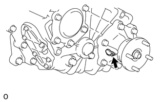
Remove the bolt and speedometer driven hole cover sub-assembly.
Remove the O-ring from the speedometer driven hole cover sub-assembly.
33403 4.REMOVE SPEEDOMETER DRIVEN GEAR SUB-ASSEMBLY (w/o ABS)
Remove the bolt and lock plate.
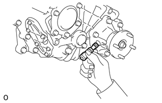
Remove the speedometer driven gear sub-assembly.
Remove the O-ring from the speedometer driven gear sub-assembly.
36124 5.REMOVE TRANSFER POWER TAKE-OFF COVER
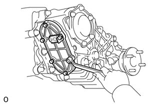
Remove the 6 bolts, transfer power take-off cover, bracket and transfer power take-off cover gasket.
6.INSPECT IDLER GEAR THRUST CLEARANCE
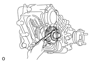
Using a feeler gauge, measure the idler gear thrust clearance.
- Standard clearance:
-
0.275 to 0.625 mm (0.0110 to 0.0246 in.)
- Maximum clearance:
-
0.625 mm (0.0246 in.)
36122 7.REMOVE NO. 2 TRANSFER CASE COVER
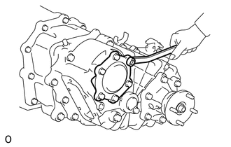
Remove the 6 bolts, No. 2 transfer case cover and transfer cover gasket.
36211B 8.REMOVE TRANSFER INPUT SHAFT NUT
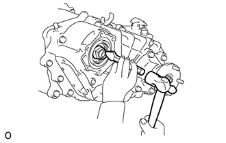
Using a chisel and hammer, loosen the staked part of the transfer input shaft nut.
Shift the outer lever of the transfer high and low shift lever to the H2 or L4 position.
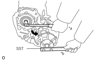
| *a | Turn |
| *b | Hold |
Using SST to hold the rear transfer output shaft companion flange, remove the transfer input shaft nut.
- SST
-
09330-00021
36104D 9.REMOVE TRANSFER OUTPUT SHAFT NUT
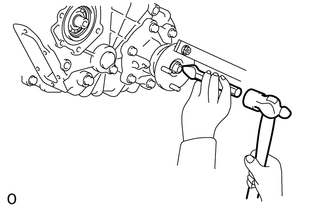
Using a chisel and hammer, loosen the staked part of the transfer output shaft nut.
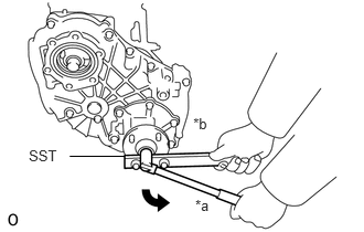
| *a | Turn |
| *b | Hold |
Using SST to hold the rear transfer output shaft companion flange, remove the transfer output shaft nut.
- SST
-
09330-00021
Remove the transfer output shaft plate washer and rear transfer output shaft companion flange.
36104B 10.REMOVE TRANSFER OUTPUT SHAFT DUST DEFLECTOR
Remove the transfer output shaft dust deflector.
36132 11.REMOVE REAR NO. 1 OUTPUT SHAFT BEARING RETAINER
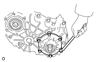
Remove the 6 bolts, rear No. 1 output shaft bearing retainer and output shaft bearing retainer gasket.
33481P 12.REMOVE TRANSFER SPEEDOMETER DRIVE GEAR
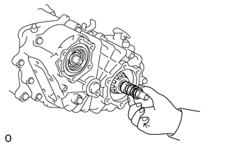
Remove the speedometer drive gear plate washer, transfer speedometer drive gear and transfer output shaft spacer.
36726 13.REMOVE TRANSFER GEAR LOCK PLATE
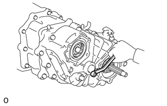
Remove the bolt and transfer gear lock plate.
36275 14.REMOVE SHIFT DETENT BALL SPRING PLUG
for Direct Shift Type:
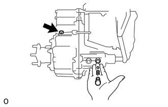
Remove the 2 shift detent ball spring plugs.
Using a magnet hand, remove the 2 shift detent ball compression springs and 2 shift detent balls.
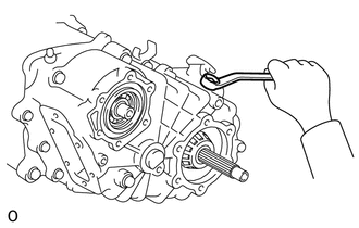
for Vacuum Shift Type:
Remove the shift detent ball spring plug.
Using a magnet hand, remove the shift detent ball compression spring and shift detent ball.
15.REMOVE REAR TRANSFER CASE
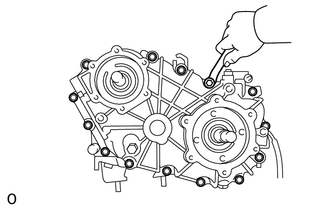
Remove the 14 bolts.
Using a plastic faced-hammer, remove the rear transfer case.
Remove the transfer case gasket from the rear transfer case.
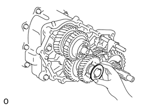
Remove the transfer idler gear side thrust washer from the transfer idler gear.
16.REMOVE OUTPUT SHAFT ASSEMBLY
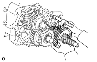
Remove the output shaft assembly and high and low shift fork shaft assembly from the front transfer case.
Remove the high and low shift fork shaft assembly from the output shaft assembly.
36212G 17.REMOVE REAR TRANSFER INPUT SHAFT RADIAL BALL BEARING
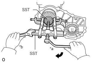
| *a | Turn |
| *b | Hold |
Using SST, remove the rear transfer input shaft radial ball bearing.
- SST
-
09950-40011 (09951-04020, 09952-04010, 09953-04020, 09954-04010, 09955-04031, 09957-04010, 09958-04011)
09950-60010 (09951-00200)
36215 18.REMOVE POWER TAKE-OFF DRIVE GEAR
Remove the power take-off drive gear.
36251 19.REMOVE TRANSFER INPUT SHAFT SPACER
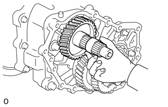
Remove the transfer input shaft spacer from the transfer input shaft.
36212 20.REMOVE TRANSFER INPUT GEAR
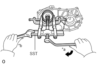
| *a | Turn |
| *b | Hold |
Using SST, remove the transfer input gear.
- SST
-
09950-40011 (09951-04020, 09952-04010, 09953-04020, 09954-04010, 09955-04031, 09957-04010, 09958-04011)
09950-60010 (09951-00200)
36221 21.REMOVE TRANSFER IDLER GEAR
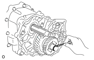
Using a screwdriver, remove the O-ring from the transfer idler gear shaft.
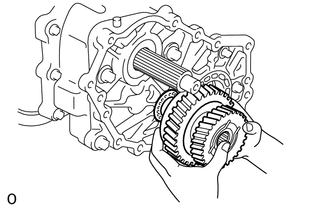
Remove the transfer idler gear.
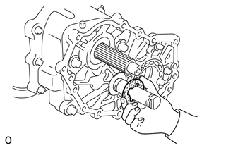
Remove the transfer idler gear side thrust washer.
36225 22.REMOVE TRANSFER IDLER GEAR SHAFT
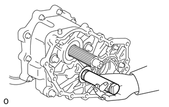
Remove the transfer idler gear shaft.
Remove the O-ring from the transfer idler gear shaft.
36134 23.REMOVE FRONT OUTPUT SHAFT BEARING RETAINER
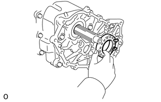
Remove the front output shaft bearing retainer from the front transfer case.
24.REMOVE FRONT TRANSFER CASE
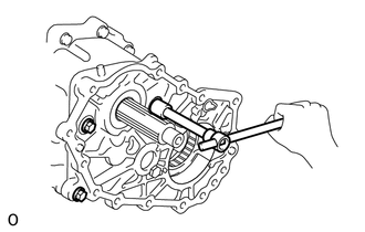
Remove the 4 bolts.
Using a plastic-faced hammer, remove the front transfer case.
Remove the transfer case gasket.
36204 25.REMOVE TRANSFER LOW SPEED OUTPUT GEAR SUB-ASSEMBLY
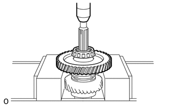
Using a press, press out the transfer output shaft taper roller bearing and transfer low speed output gear sub-assembly.
36235 26.REMOVE TRANSFER HIGH AND LOW CLUTCH SLEEVE
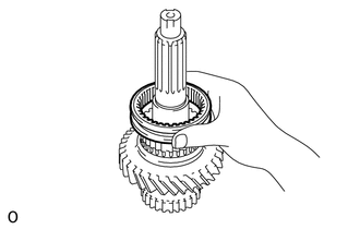
Remove the transfer high and low clutch sleeve.
36203 27.REMOVE TRANSFER HIGH SPEED OUTPUT GEAR SUB-ASSEMBLY
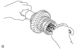
Using a snap ring expander, remove the transfer output shaft snap ring.
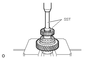
Using a press and SST, press out the transfer clutch hub, transfer output shaft taper roller bearing and transfer high speed output gear sub-assembly.
- SST
-
09950-60010 (09951-00300)
09950-70010 (09951-07100)
- HINT:
-
Support the output shaft assembly by hand to prevent it from dropping.
36314 28.REMOVE TRANSFER HIGH AND LOW SHIFT FORK SHAFT
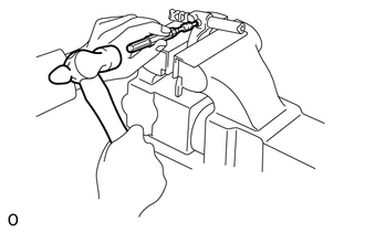
Using a pin punch and hammer, tap out the transfer shift fork slotted spring pin.
Remove the transfer high and low shift fork shaft from the No. 2 transfer gear shift fork.
36231E 29.REMOVE FRONT TRANSFER OUTPUT SHAFT NEEDLE ROLLER BEARING
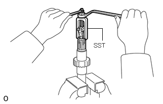
Using SST, remove the front transfer output shaft needle roller bearing.
- SST
-
09319-60020
36221B 30.REMOVE TRANSFER IDLER GEAR BEARING
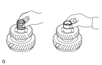
Remove the 2 transfer idler gear bearings and transfer idler gear spacer.
36119A 31.REMOVE TRANSFER IDLER GEAR TRANSFER OIL RECEIVER
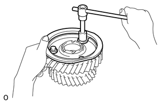
Remove the 3 bolts and transfer idler gear transfer oil receiver from the transfer idler gear.
36231C 32.REMOVE TRANSFER OUTPUT SHAFT TAPER ROLLER BEARING
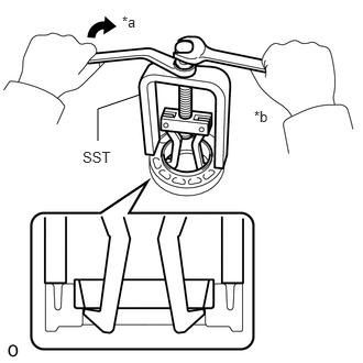
| *a | Turn |
| *b | Hold |
for High Gear Side:
Using SST, remove the transfer output shaft taper roller bearing (outer race) from the output shaft front bearing retainer.
- SST
-
09514-35011
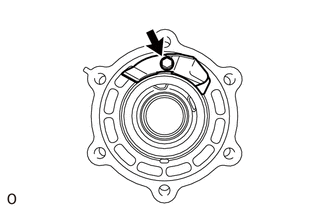
for Low Gear Side:
Remove the bolt and No. 1 transfer oil receiver from the rear No. 1 output shaft bearing retainer.
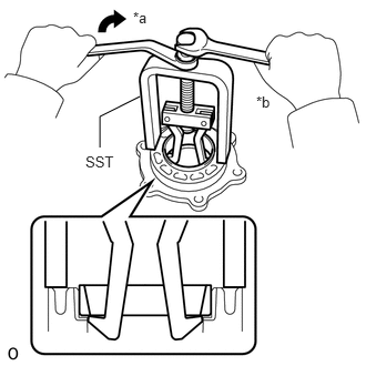
| *a | Turn |
| *b | Hold |
Using SST, remove the transfer output shaft taper roller bearing (outer race) and transfer output shaft shim from the rear No. 1 output shaft bearing retainer.
- SST
-
09514-35011
36132A 33.REMOVE OUTPUT SHAFT RETAINER OIL SEAL
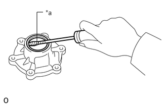
| *a | Protective Tape |
Using a screwdriver, remove the output shaft retainer oil seal.
- HINT:
-
Tape the screwdriver tip before use.
33404E 34.REMOVE SPEEDOMETER SHAFT SLEEVE OIL SEAL (w/o ABS)
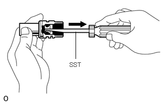
Using SST, remove the speedometer shaft sleeve oil seal.
- SST
-
09921-00011
36410 35.REMOVE DIAPHRAGM CYLINDER ASSEMBLY (for Vacuum Shift Type)
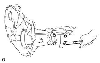
Remove the 4 bolts, diaphragm cylinder assembly and diaphragm cylinder gasket.
36337 36.REMOVE FRONT DRIVE SHIFT LINK LEVER (for Vacuum Shift Type)
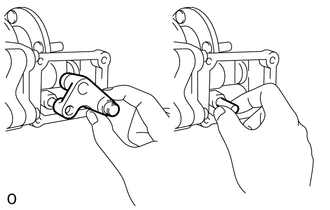
Remove the front drive shift link lever and front drive shift link lever straight pin.
37.REMOVE DIAPHRAGM CYLINDER BODY (for Vacuum Shift Type)
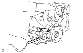
Remove the 4 bolts, diaphragm cylinder body and transfer shift shaft guide gasket.
36343A 38.REMOVE FRONT VACUUM MAGNET TYPE DRIVE SHIFT LINK LEVER SHOE (for Vacuum Shift Type)
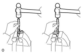
Using pin punch and hammer, tap out the 2 front vacuum magnet type drive shift link lever shoes from the front drive shift link lever.
36318 39.REMOVE FRONT TRANSFER DRIVE SHIFT BOOT (for Direct Shift Type)
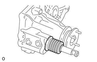
Remove the front transfer drive shift boot from the front transfer case.
36236 40.REMOVE FRONT DRIVE CLUTCH SLEEVE
Remove the front drive clutch sleeve with the No. 1 transfer gear shift fork.
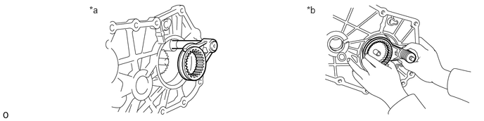
| *a | for Direct Shift Type | *b | for Vacuum Shift Type |
36311 41.REMOVE NO. 1 TRANSFER GEAR SHIFT FORK
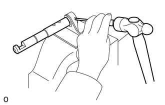
for Direct Shift Type:
Using a pin punch and hammer, tap out the transfer shift fork slotted spring pin from the No. 1 transfer gear shift fork.
Remove the No. 1 transfer gear shift fork from the front transfer drive shift shaft.
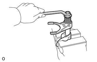
for Vacuum Shift Type:
Remove the bolt, plate washer, front transfer drive shift shaft compression spring and No. 1 transfer gear shift fork from the front transfer drive shift shaft.
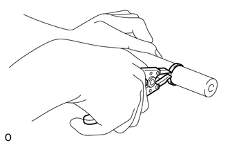
Using snap ring pliers, remove the snap ring from the front transfer drive shift shaft.
36211 42.REMOVE TRANSFER INPUT SHAFT
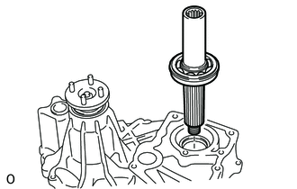
Remove the transfer input shaft from the front transfer case.
Remove the O-ring from the transfer input shaft.
36212F 43.REMOVE FRONT TRANSFER INPUT SHAFT RADIAL BALL BEARING
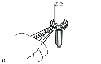
Using a snap ring expander, remove the snap ring from the transfer input shaft.
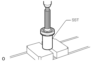
Using SST and a press, remove the front transfer input shaft radial ball bearing from the transfer input shaft.
- SST
-
09523-36010
36104 44.REMOVE TRANSFER OUTPUT SHAFT COMPANION FLANGE
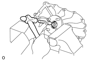
Using a hammer and chisel, stake the transfer output shaft nut.
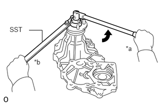
| *a | Turn |
| *b | Hold |
Using SST to hold the transfer output shaft companion flange, remove the transfer output shaft nut.
- SST
-
09330-00021
Remove the transfer output shaft plate washer and transfer output shaft companion flange.
36234 45.REMOVE FRONT TRANSFER OUTPUT SHAFT
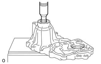
Using a press, press out the front transfer output shaft.
36111B 46.REMOVE TRANSFER CASE OIL SEAL
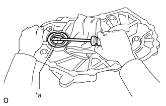
| *a | Protective Tape |
Using a screwdriver, remove the transfer case oil seal.
- HINT:
-
Tape the screwdriver tip before use.
36313J 47.REMOVE FRONT TRANSFER DRIVE SHIFT SHAFT OIL SEAL (for Direct Shift Type)
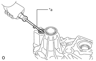
| *a | Protective Tape |
Using a screwdriver, remove the front transfer drive shift shaft oil seal.
- HINT:
-
Tape the screwdriver tip before use.
36134A 48.REMOVE FRONT OUTPUT SHAFT BEARING RETAINER OIL SEAL
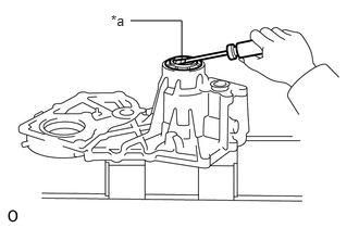
| *a | Protective Tape |
Using a screwdriver, remove the front output shaft bearing retainer oil seal.
- HINT:
-
Tape the screwdriver tip before use.
36234A 49.REMOVE FRONT TRANSFER OUTPUT SHAFT BEARING
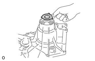
Remove the No. 2 transfer oil receiver.
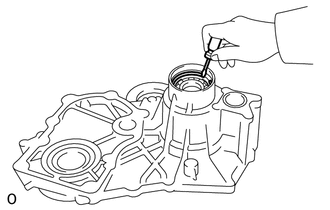
Using a screwdriver, remove the front transfer output shaft bearing snap ring.
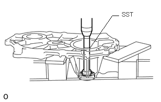
Using SST and a press, press out the front transfer output shaft bearing.
- SST
-
09950-60010 (09951-00450)
09950-70010 (09951-07200)
36486 50.REMOVE SUCTION TUBE (for Vacuum Shift Type)
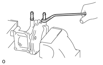
Remove the 2 suction tubes and 2 suction tube gaskets from the diaphragm cylinder and diaphragm cylinder cover.
51.REMOVE DIAPHRAGM CYLINDER COVER (for Vacuum Shift Type)
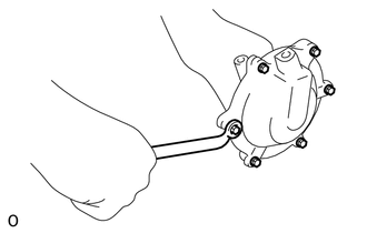
Remove the 6 bolts and diaphragm cylinder cover.
36422 52.REMOVE TRANSFER DIAPHRAGM PLATE (for Vacuum Shift Type)
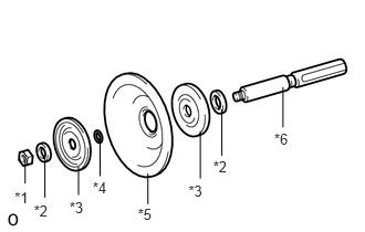
| *1 | Nut |
| *2 | Plate Washer |
| *3 | Transfer Diaphragm Plate |
| *4 | Diaphragm Push Rod O-ring |
| *5 | Diaphragm Cylinder Diaphragm |
| *6 | Diaphragm Push Rod |
Remove the nut, 2 plate washers, 2 transfer diaphragm plates, diaphragm cylinder diaphragm and diaphragm push rod O-ring from the diaphragm push rod.
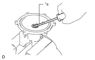
| *a | Protective Tape |
Using a screwdriver, remove the diaphragm push rod type T seal.
- HINT:
-
Tape the screwdriver tip before use.
36362 53.REMOVE TRANSFER HIGH AND LOW SHIFT OUTER LEVER
Remove the nut, spring washer, 2 plate washers and bolt.
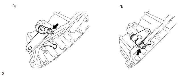
| *a | for Direct Shift Type | *b | for Vacuum Shift Type |
Remove the transfer high and low shift outer lever and washer.
Remove the high and low shift inner lever sub-assembly.
36307A 54.REMOVE HIGH AND LOW SHIFT INNER LEVER OIL SEAL
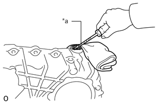
| *a | Protective Tape |
Using a screwdriver, remove the high and low shift inner lever oil seal.
- HINT:
-
Tape the screwdriver tip before use.