BF1B TRANSFER / 4WD / AWD TRANSFER CONTROL SOLENOID INSPECTION
PROCEDURE

 85440A 1.INSPECT FOUR WHEEL DRIVE CONTROL SOLENOID ASSEMBLY
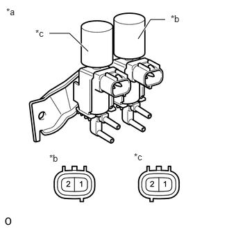
| *a | Component without harness connected (Four Wheel Drive Control Solenoid Assembly) |
| *b | VSV2 |
| *c | VSV4 |
Measure the resistance according to the value(s) in the table below.
- Standard Resistance:
-
Tester Connection Condition Specified Condition 1 - 2 20 °C (68 °F) 37.0 to 44.0 Ω
If the result is not as specified, replace the four wheel drive control solenoid assembly.
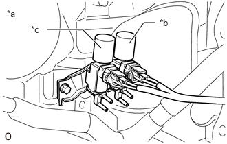
| *a | Component with harness connected (Four Wheel Drive Control Solenoid Assembly) |
| *b | VSV2 |
| *c | VSV4 |
Airflow check
When the transmission control switch is turned off, check that there is airflow from the VSV2 side and no airflow from the VSV4 side.
When the transmission control switch is turned on, check that there is airflow from the VSV4 side and no airflow from the VSV2 side.
If the result is not as specified, replace the four wheel drive control solenoid assembly.
85917 2.INSPECT FRONT DRIVE RELAY
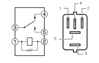
Measure the resistance according to the value(s) in the table below.
- Standard Resistance:
-
Tester Connection Condition Specified Condition 3 - 4 Battery voltage not applied between terminals 1 and 2 Below 1 Ω Battery voltage applied between terminals 1 and 2 10 kΩ or higher 3 - 5 Battery voltage not applied between terminals 1 and 2 10 kΩ or higher Battery voltage applied between terminals 1 and 2 Below 1 Ω
If the result is not as specified, replace the change relay.