H150F MANUAL TRANSMISSION / TRANSAXLE OUTPUT SHAFT INSPECTION
PROCEDURE

 1.INSPECT 1ST GEAR THRUST CLEARANCE
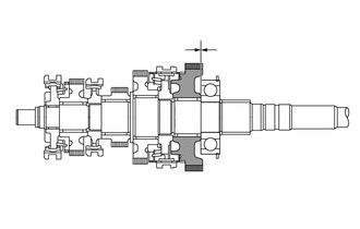
Using a dial indicator, measure the 1st gear thrust clearance.
- Standard Clearance:
-
0.10 to 0.45 mm (0.00394 to 0.01771 in.)
- Maximum Clearance:
-
0.45 mm (0.01771 in.)
If the clearance more than the maximum, replace the 1st gear, No. 1 transmission clutch hub and rear output shaft bearing with new ones.
2.INSPECT 2ND GEAR THRUST CLEARANCE
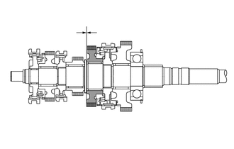
Using a dial indicator, measure the 2nd gear thrust clearance.
- Standard Clearance:
-
0.10 to 0.35 mm (0.00394 to 0.01377 in.)
- Maximum Clearance:
-
0.35 mm (0.01377 in.)
If the clearance more than the maximum, replace the 2nd gear, No. 1 transmission clutch hub and output shaft with new ones.
3.INSPECT 3RD GEAR THRUST CLEARANCE
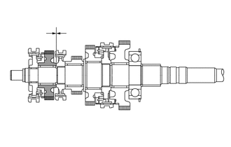
Using a dial indicator, measure the 3rd gear thrust clearance.
- Standard Clearance:
-
0.10 to 0.45 mm (0.00394 to 0.01771 in.)
- Maximum Clearance:
-
0.45 mm (0.01771 in.)
If the clearance more than the maximum, replace the 3rd gear, No. 2 transmission clutch hub and No. 3 transmission clutch hub with new ones.
4.INSPECT 5TH GEAR THRUST CLEARANCE
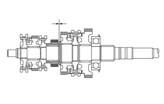
Using a dial indicator, measure the 5th gear thrust clearance.
- Standard Clearance:
-
0.10 to 0.35 mm (0.00394 to 0.01377 in.)
- Maximum Clearance:
-
0.35 mm (0.01377 in.)
If the clearance more than the maximum, replace the 5th gear, No. 3 transmission clutch hub and output with new ones.
5.INSPECT 1ST GEAR RADIAL CLEARANCE
Mount the output shaft assembly in a vise between aluminum plates.
- NOTICE:
-
Do not overtighten the vise.
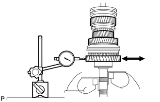
Using a dial indicator, measure the 1st gear radial clearance.
- Standard Clearance:
-
0.020 to 0.073 mm (0.000788 to 0.002874 in.)
- Maximum Clearance:
-
0.073 mm (0.002874 in.)
If the clearance more than the maximum, replace the 1st gear, 1st gear needle roller bearing and output shaft with new ones.
6.INSPECT 2ND GEAR RADIAL CLEARANCE
Mount the output shaft assembly in a vise between aluminum plates.
- NOTICE:
-
Do not overtighten the vise.
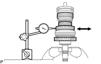
Using a dial indicator, measure the 2nd gear radial clearance.
- Standard Clearance:
-
0.020 to 0.068 mm (0.000788 to 0.002677 in.)
- Maximum Clearance:
-
0.068 mm (0.002677 in.)
If the clearance more than the maximum, replace the 2nd gear, 2nd gear needle roller bearing and output shaft with new ones.
7.INSPECT 3RD GEAR RADIAL CLEARANCE
Mount the output shaft assembly in a vise between aluminum plates.
- NOTICE:
-
Do not overtighten the vise.
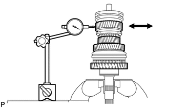
Using a dial indicator, measure the 3rd gear radial clearance.
- Standard Clearance:
-
0.020 to 0.073 mm (0.000788 to 0.002874 in.)
- Maximum Clearance:
-
0.073 mm (0.002874 in.)
If the clearance more than the maximum, replace the 3rd gear, 3rd gear needle roller bearing and output shaft with new ones.
8.INSPECT 5TH GEAR RADIAL CLEARANCE
Mount the output shaft assembly in a vise between aluminum plates.
- NOTICE:
-
Do not overtighten the vise.
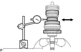
Using a dial indicator, measure the 5th gear radial clearance.
- Standard Clearance:
-
0.020 to 0.068 mm (0.000788 to 0.002677 in.)
- Maximum Clearance:
-
0.068 mm (0.002677 in.)
If the clearance more than the maximum, replace the 5th gear, 5th gear needle roller bearing and output shaft with new ones.
33321 9.INSPECT OUTPUT SHAFT
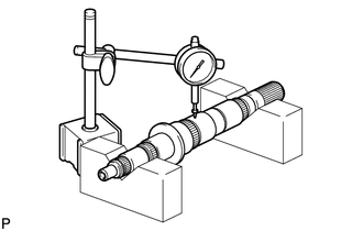
Using a dial indicator, measure the output shaft and measure the runout of the output shaft.
- Maximum Runout:
-
0.03 mm (0.00118 in.)
If the runout is more than the maximum, replace the output shaft with a new one.
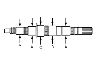
Using a micrometer, measure the journal diameter of the output shaft journal surface.
- Standard Outside Diameter:
-
Measuring Point Specified Condition Minimum Diameter A 37.979 to 37.995 mm (1.4953 to 1.4958 in.) 37.979 mm (1.4953 in.) B 45.984 to 46.000 mm (1.8104 to 1.8110 in.) 45.984 mm (1.8104 in.) C 57.984 to 58.000 mm (2.2829 to 2.2834 in.) 57.984 mm (2.2829 in.) D 49.979 to 49.995 mm (1.9677 to 1.9683 in.) 49.979 mm (1.9677 in.) E 44.484 to 44.500 mm (1.7514 to 1.7519 in.) 44.484 mm (1.7514 in.)
If the outside diameter is not as specified, replace the output shaft with a new one.
33335 10.INSPECT 1ST GEAR
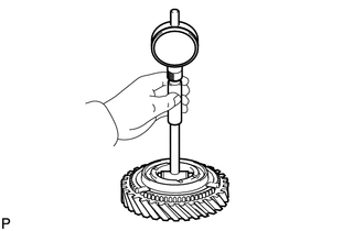
Using a cylinder gauge, measure the inside diameter of the 1st gear.
- Standard Inside Diameter:
-
57.015 to 57.040 mm (2.2447 to 2.2456 in.)
- Maximum Inside Diameter:
-
57.040 mm (2.2456 in.)
If the inside diameter is more than the maximum, replace the 1st gear with a new one.
33332 11.INSPECT 2ND GEAR
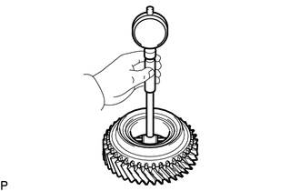
Using a cylinder gauge, measure the inside diameter of the 2nd gear.
- Standard Inside Diameter:
-
65.015 to 65.040 mm (2.5597 to 2.5606 in.)
- Maximum Inside Diameter:
-
65.040 mm (2.5606 in.)
If the inside diameter is more than the maximum, replace the 2nd gear with a new one.
33333 12.INSPECT 3RD GEAR
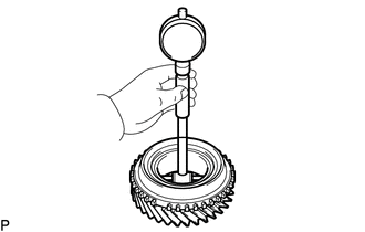
Using a cylinder gauge, measure the inside diameter of the 3rd gear.
- Standard Inside Diameter:
-
44.015 to 44.040 mm (1.7329 to 1.7338 in.)
- Maximum Inside Diameter:
-
44.040 mm (1.7338 in.)
If the inside diameter is more than the maximum, replace the 3rd gear with a new one.
33336 13.INSPECT 5TH GEAR
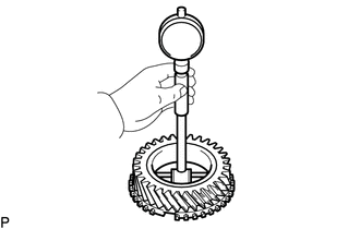
Using a cylinder gauge, measure the inside diameter of the 5th gear.
- Standard Inside Diameter:
-
53.015 to 53.040 mm (2.0873 to 2.0881 in.)
- Maximum Inside Diameter:
-
53.040 mm (2.0881 in.)
If the inside diameter is more than the maximum, replace the 5th gear with a new one.
33363 14.INSPECT NO. 1 TRANSMISSION HUB SLEEVE
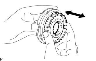
Install the No. 1 transmission hub sleeve to the No. 1 transmission clutch hub and check that the parts slide smoothly.
- HINT:
-
If the parts do not slide smoothly, replace the No. 1 transmission hub sleeve and No. 1 transmission clutch hub.
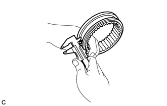
Using a vernier caliper, measure the No. 1 hub sleeve groove.
- Standard Clearance:
-
12.0 to 12.1 mm (0.4725 to 0.4763 in.)
- Maximum Diameter:
-
12.1 mm (0.4763 in.)
If the clearance is not as specified, replace the No. 1 hub sleeve.
Check that the tip of the spline gear of the No. 1 transmission hub sleeve is not worn.
- HINT:
-
If worn, replace the No. 1 transmission hub sleeve with a new one.
36235B 15.INSPECT NO. 2 TRANSMISSION HUB SLEEVE
Install the No. 2 transmission hub sleeve to the No. 2 transmission clutch hub and check that the parts slide smoothly.
- HINT:
-
If the parts do not slide smoothly, replace the No. 2 transmission hub sleeve and No. 2 transmission clutch hub with new ones
Using a vernier caliper, measure the No. 2 hub sleeve groove.
- Standard Clearance:
-
12.0 to 12.1 mm (0.4725 to 0.4763 in.)
- Maximum Diameter:
-
12.1 mm (0.4763 in.)
If the clearance is not as specified, replace the No. 2 hub sleeve.
Check that the tip of the spline gear of the No. 2 transmission hub sleeve is not worn.
- HINT:
-
If worn, replace the No. 2 transmission hub sleeve with a new one.
33395 16.INSPECT NO. 3 TRANSMISSION HUB SLEEVE
Install the No. 3 transmission hub sleeve to the No. 3 transmission clutch hub and check that the parts slide smoothly.
- HINT:
-
If the parts do not slide smoothly, replace the No. 3 transmission hub sleeve and No. 3 transmission clutch hub with new ones.
Using a vernier caliper, measure the No. 3 hub sleeve groove.
- Standard Clearance:
-
10.5 to 10.6 mm (0.4134 to 0.4173 in.)
- Maximum Diameter:
-
10.6 mm (0.4173 in.)
If the clearance is not as specified, replace the No. 3 hub sleeve.
Check that the tip of the spline gear of the No. 3 transmission hub sleeve is not worn.
- HINT:
-
If worn, replace the No. 3 transmission hub sleeve with a new one.
33038E 17.INSPECT NO. 2 SYNCHRONIZER RING SET
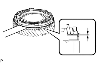
Using a thickness gauge, check the clearance between the No. 2 synchronizer ring set and 2nd gear when the No. 2 synchronizer ring set is pressed onto the tapered cone of the 2nd gear by hand.
- Standard Clearance:
-
1.23 to 2.13 mm (0.0485 to 0.0838 in.)
- Minimum Clearance:
-
1.23 mm (0.0485 in.)
- NOTICE:
-
Make sure to perform the measurement along the entire circumference of the 2nd gear.
- HINT:
-
If the clearance is less than the minimum, replace the No. 2 synchronizer ring set.
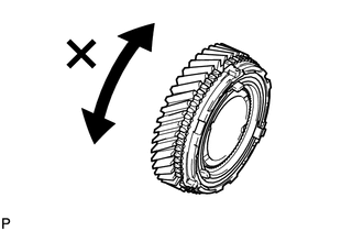
Apply gear oil to the 2nd gear and tapered cone of the No. 2 synchronizer ring set. Then press the No. 2 synchronizer ring set by hand and check that the No. 2 synchronizer ring set does not slip when rotated along the circumference.
- HINT:
-
If slippage occurs, replace the No. 2 synchronizer ring set with a new one.
33039 18.INSPECT NO. 3 SYNCHRONIZER RING SET
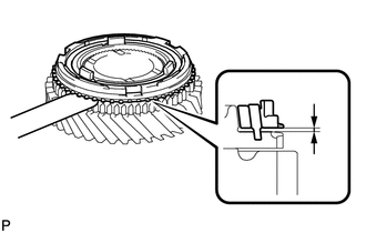
Using a thickness gauge, check the clearance between the No. 3 synchronizer ring set and 3rd gear when the No. 3 synchronizer ring set is pressed onto the tapered cone of the 3rd gear by hand.
- Standard Clearance:
-
1.15 to 2.05 mm (0.0453 to 0.0807 in.)
- Minimum Clearance:
-
1.15 mm (0.0453 in.)
- NOTICE:
-
Make sure to perform the measurement along the entire circumference of the 3rd gear.
- HINT:
-
If the clearance is less than the minimum, replace the No. 3synchronizer ring.
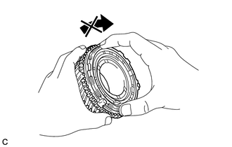
Apply gear oil to the 3rd gear and the tapered cone of No. 3 synchronizer ring set. Then press the No. 3 synchronizer ring set by hand and check that the No. 3 synchronizer ring set does not slip when rotated along the circumference.
- HINT:
-
If slippage occurs, replace the No. 3 synchronizer ring set with a new one.
33367 19.INSPECT NO. 1 SYNCHRONIZER RING
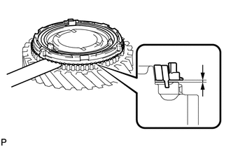
Using a thickness gauge, check the clearance between the No. 1 synchronizer ring and 1st gear when the No. 1 synchronizer ring is pressed onto the tapered cone of the 1st gear by hand.
- Standard Clearance:
-
1.1 to 1.9 mm (0.0434 to 0.0748 in.)
- Minimum Clearance:
-
1.1 mm (0.0434 in.)
- NOTICE:
-
Make sure to perform the measurement along the entire circumference of the 1st gear.
- HINT:
-
If the clearance is less than the minimum, replace the No. 1 synchronizer ring.
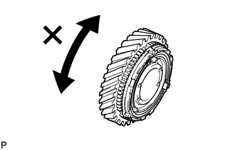
Apply gear oil to the 1st gear and tapered cone of the No. 1 synchronizer ring. Then press the No. 1 synchronizer ring by hand and check that the No. 1 synchronizer ring does not slip when rotated along the circumference.
- HINT:
-
If slippage occurs, replace the No. 1 synchronizer ring with a new one.
33369 20.INSPECT NO. 3 SYNCHRONIZER RING
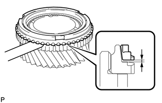
Using a thickness gauge, check the clearance between the No. 3 synchronizer ring and 5th gear when the No. 3 synchronizer ring is pressed onto the tapered cone of the 5th gear by hand.
- Standard Clearance:
-
0.80 to 1.60 mm (0.0315 to 0.0629 in.)
- Minimum Clearance:
-
0.80 mm (0.0315 in.)
- NOTICE:
-
Make sure to perform the measurement along the entire circumference of the 5th gear.
- HINT:
-
If the clearance is less than the minimum, replace the No. 3 synchronizer ring.
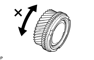
Coat the 5th gear cone with gear oil. Check the braking effect of the synchronizer ring. Turn the synchronizer ring in one direction while pushing it to the 5th gear cone. Check that the ring locks.
- HINT:
-
If slippage occurs, replace the No. 3 synchronizer ring with a new one.