RM25T0E _59 Vehicle Exterior _029940 LIGHTING (EXT) _0138190 TURN SIGNAL FLASHER ASSEMBLY G
LIGHTING (EXT) TURN SIGNAL FLASHER ASSEMBLY ON-VEHICLE INSPECTION
PROCEDURE

 81980 1.INSPECT TURN SIGNAL FLASHER ASSEMBLY
a.
Disconnect the connector from the turn signal flasher assembly.
b.
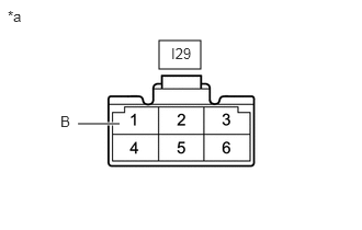
1.51,0.385 1.906,0.656 0.396,0.271 0.74,1.177 1.135,1.177 true 0.073,0.073 0.385,0.229 0.313,0.156 10 false *a 0.573,1.073 0.729,1.271 0.156,0.198 10 false B 1.625,0.427 2.083,0.625 0.458,0.198 10 false I29
| *a | Front view of wire harness connector (to Turn Signal Flasher Assembly) |
Measure the voltage on the wire harness side connector according to the value(s) in the table below.
- Standard Voltage:
-
Tester Connection Condition Specified Condition I29-1 (B) - Body ground Always 22 to 26 V
If the result is not as specified, repair or replace the wire harness or connector.
c.
Connect the connector to the turn signal flasher assembly.
d.
Turn the ignition switch to ON.
e.
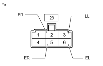
1.479,0.469 1.938,0.698 0.458,0.229 1.573,1.104 1.25,0.49 1.25,0.49 0.833,0.49 true 2.271,1.146 2.375,0.531 2.375,0.531 2.76,0.531 true 2.271,1.448 2.427,1.927 2.427,1.927 2.76,1.927 true 1.583,1.448 1.5,1.927 1.5,1.927 1.063,1.927 true 0.073,0.073 0.385,0.229 0.313,0.156 10 false *a 1.615,0.51 2.073,0.708 0.458,0.198 10 false I29 0.594,0.406 0.906,0.604 0.313,0.198 10 false FR 2.833,0.448 3.146,0.646 0.313,0.198 10 false LL 2.844,1.833 3.156,2.031 0.313,0.198 10 false EL 0.802,1.833 1.115,2.031 0.313,0.198 10 false ER
| *a | Rear view of wire harness connector (to Turn Signal Flasher Assembly) |
Measure the voltage according to the value(s) in the table below.
- Standard Voltage:
-
Tester Connection Switch Condition Specified Condition I29-2 (FR) - Body ground Hazard warning switch off Below 1 V Hazard warning switch on Alternating between 22 to 26 V and below 1 V
(60 to 120 times per minute)Turn signal switch right turn position Alternating between 22 to 26 V and below 1 V
(60 to 120 times per minute)I29-3 (LL) - Body ground Hazard warning switch off Below 1 V Hazard warning switch on Alternating between 22 to 26 V and below 1 V
(60 to 120 times per minute)Turn signal switch left turn position Alternating between 22 to 26 V and below 1 V
(60 to 120 times per minute)I29-5 (ER) - Body ground Turn signal switch neutral position 18 V or higher Turn signal switch right turn position Below 1 V I29-6 (EL) - Body ground Turn signal switch neutral position 18 V or higher Turn signal switch left turn position Below 1 V
If the result is not as specified, replace the turn signal flasher assembly.