STEERING GEAR / LINKAGE STEERING GEAR(w/ Driver Side Knee Airbag) DISASSEMBLY
CAUTION / NOTICE / HINT
- NOTICE:
-
·
When using a vise, place aluminum plates between the part and vise.
·When using a vise, do not overtighten it.
PROCEDURE

 44251 1.REMOVE PITMAN ARM
Remove the sector shaft to pitman arm setting hexagon nut.
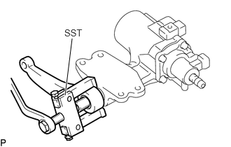
Using SST, disconnect the pitman arm.
- SST
-
09628-62011
44110 2.FIX POWER STEERING GEAR ASSEMBLY
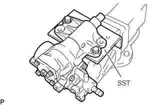
Fix the power steering gear assembly on SST and clamp SST in a vise.
- SST
-
09630-00014 (09631-00142)
44154 3.REMOVE POWER PISTON PLUNGER GUIDE NUT
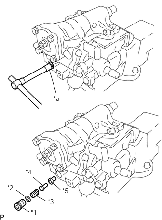
| *1 | Power Piston Plunger Guide Nut |
| *2 | O-ring |
| *3 | Power Piston Plunger Compression Spring |
| *4 | Power Piston Plunger |
| *5 | Power Piston Plunger Guide |
| *a | Hexagon Socket Wrench |
Using a 10 mm hexagon socket wrench, remove the power piston plunger guide nut.
Remove the O-ring from the power piston plunger guide nut.
Remove the power piston plunger compression spring, power piston plunger and power piston plunger guide.
44108 4.REMOVE SIDE COVER SUB-ASSEMBLY
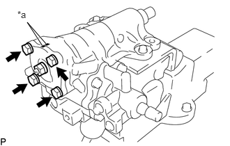
| *a | Matchmark |
Remove the lock nut and cross shaft adjusting screw seal washer.
Put matchmarks on the power steering gear housing sub-assembly and side cover sub-assembly.
Remove the 4 bolts.
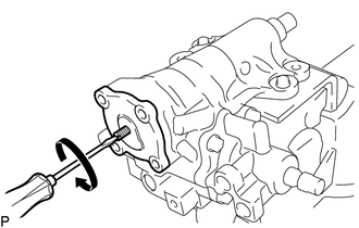
Turn the sector shaft adjusting screw clockwise and remove the side cover sub-assembly.
Remove the O-ring from the side cover sub-assembly.
44111 5.REMOVE CROSS SHAFT
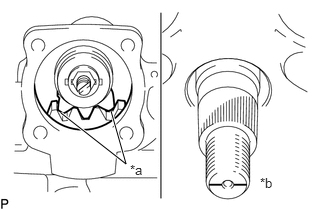
| *a | Do not contact |
| *b | Parallel with Installation Surface |
When pulling out the cross shaft, do so at an angle that ensures that the part of the cross shaft indicated in the illustration does not contact the power steering gear housing sub-assembly (center position).
- HINT:
-
When the stamp on the cross shaft is parallel to the power steering gear assembly, the cross shaft is in the center position.
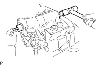
| *a | Protective Tape |
Wrap the threaded portion and serrations of the cross shaft with protective tape.
Using a plastic-faced hammer, tap on the cross shaft end and pull out the cross shaft.
44120 6.REMOVE VALVE ASSEMBLY (WITH BALL NUT)
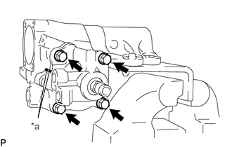
| *a | Matchmark |
Put matchmarks on the valve assembly (with ball nut) and power steering gear housing.
Remove the 4 bolts.
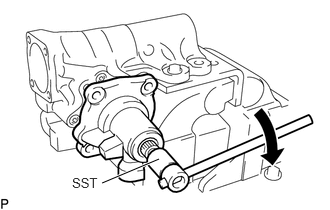
Using SST, turn the shaft clockwise to disconnect the valve assembly (with ball nut), and then lift it up approximately 6 mm.
- SST
-
09616-00011
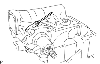
Pull the valve assembly (with ball nut) towards you to create a gap of approximately 12 mm between it and the power steering gear housing sub-assembly.
Insert the handle of a thin-bladed screwdriver into the gap between the valve assembly (with ball nut) and power steering gear housing sub-assembly.
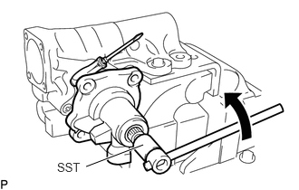
Using SST, lightly turn the shaft counterclockwise until it locks.
- SST
-
09616-00011
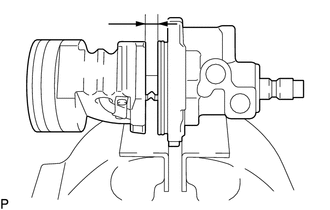
Pull the valve assembly (with ball nut) towards you to remove it.
- NOTICE:
-
·
Do not separate the power piston nut and valve assembly (with ball nut) by more than 45 mm.
-
·
If the power piston nut is faced downward, it may fall off under its own weight or the ball may drop inside the piston nut.
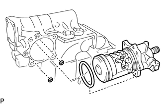
Remove the 2 O-rings from the power steering gear housing.
Remove the O-ring from the valve housing of the valve assembly (with ball nut).
44107A 7.REMOVE POWER STEERING GEAR HOUSING NEEDLE ROLLER BEARING
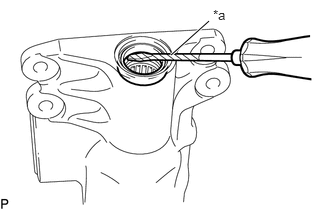
| *a | Protective Tape |
Using a screwdriver with its tip wrapped in protective tape, pry out the power steering housing oil seal.
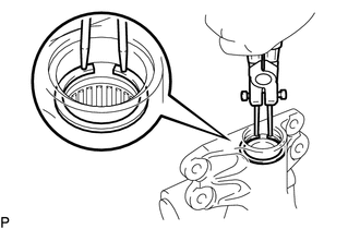
Using snap ring pliers, remove the power steering gear housing hole snap ring.
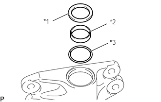
| *1 | Power Steering Gear Housing Ring |
| *2 | Power Steering Gear Housing Ring ("Teflon" Ring) |
| *3 | O-ring |
Remove the power steering gear housing ring, power steering gear housing ring ("Teflon" Ring) and O-ring.
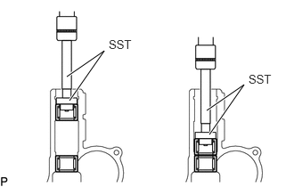
Using SST, press in the power steering gear housing needle roller bearing (lower).
- SST
-
09950-60010 (09951-00350, 09951-00420, 09952-06010)
09950-70010 (09951-07100)
Using SST, press out the power steering gear housing needle roller bearing (lower) and steering gear housing needle roller bearing (upper).
- SST
-
09950-60010 (09951-00350, 09951-00420, 09952-06010)
09950-70010 (09951-07100)
- NOTICE:
-
Make sure to press the power steering gear housing needle roller bearing (lower) straight into the steering gear housing needle roller bearing (upper).
44114A 8.REMOVE POWER PISTON NUT RING ("TEFLON" RING)
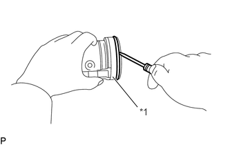
| *1 | Power Piston Nut |
Using a screwdriver, remove the power piston nut ring ("Teflon" Ring) and O-ring.
- NOTICE:
-
Be careful not to damage the power piston nut.
44105C 9.REMOVE VALVE BODY HOUSING UNION SEAT
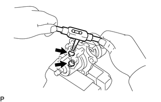
Using a screw extractor, remove the 2 valve body housing union seats.
- NOTICE:
-
·
Do not allow any shards into the port.
·In order to prevent shards, forcefully push down on the screw extractor, and then turn a very small amount to the left to pull out the valve body housing union sheet.
·If the screw extractor is too small, the valve assembly port will be damaged.
- HINT:
-
The valve body housing union seat has an inner diameter of 6 mm.
45357 10.REMOVE SECTOR SHAFT ADJUSTING SCREW
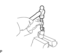
Using a chisel and hammer, remove the lock nut stake.
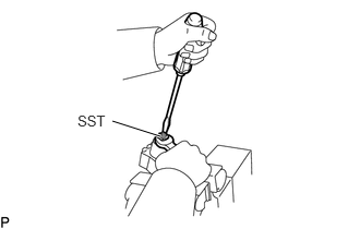
Using SST, remove the lock nut.
- SST
-
09630-00014 (09631-00051)