STEERING GEAR / LINKAGE STEERING LINKAGE INSTALLATION
CAUTION / NOTICE / HINT
- NOTICE:
-
·
When using a vise, place aluminum plates between the part and vise.
·When using a vise, do not overtighten it.
- HINT:
-
·
Use the same procedure for RHD and LHD vehicles.
·The procedure listed below is for LHD vehicles.
PROCEDURE

 45045 1.INSTALL STEERING RELAY ROD END SUB-ASSEMBLY LH
When reassembling steering relay rod end:
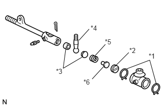
| *1 | Relay Rod Set Ring |
| *2 | Steering Link Joint Straight Screw Plug |
| *3 | Ball Stud Seat |
| *4 | Steering Link Joint Knob |
| *5 | Steering Link Joint Compression Spring |
| *6 | Steering Link Joint Spring Seat |
Apply MP grease to the joint parts.
Install the steering link joint compression spring, steering link joint spring seat, steering link joint knob, 2 ball stud seats and steering link joint screw plug.
Tighten the steering link joint screw plug fully, and then loosen the steering link joint screw plug 1/2 turn.
Install the 2 relay rod set rings.
Pack the steering relay rod end with MP grease.
- Grease capacity:
-
4.8 to 6.2 g (0.170 to 0.218 oz.)
Screw the steering relay rod end into the steering relay rod.
45044 2.INSTALL STEERING RELAY ROD END SUB-ASSEMBLY RH
- HINT:
-
Use the same procedures described for the LH side.
45450 3.ADJUST STEERING RELAY ROD ASSEMBLY
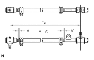
| *a | Length |
w/o Driver Side Knee Airbag:
Turn the steering relay rod ends equal amounts into the steering relay rod, and adjust the length of the steering relay rod.
- Length:
-
1107.5 to 1110.5 mm (3.633 to 3.642 ft.)
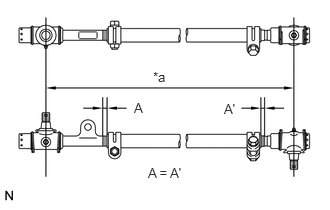
| *a | Length |
w/ Driver Side Knee Airbag:
Turn the steering relay rod ends equal amounts into the steering relay rod, and adjust the length of the steering relay rod.
- Length:
-
1086.5 to 1089.5 mm (3.564 to 3.573 ft.)
Temporarily tighten the bolts or nuts to fix the clamps in place so that the steering relay rod ends are as shown in the illustration.
45047 4.INSTALL TIE ROD END SUB-ASSEMBLY LH
Screw the tie rod end LH into the tie rod.
45046 5.INSTALL TIE ROD END SUB-ASSEMBLY RH
Screw the tie rod end RH into the tie rod.
45460A 6.ADJUST TIE ROD ASSEMBLY
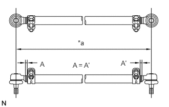
| *a | Length |
Turn the tie rod ends equal amounts into the steering tie rod, and adjust the length of the steering tie rod.
- Length:
-
1184.5 mm (3.89 ft.)
Temporarily tighten the bolts or nuts to fix the clamps in place so that the rod ends are as shown in the illustration.
After toe-in adjustment, tighten the 2 bolts and 2 nuts to tighten the 2 clamps.
- Torque:
- 36.8 N*m (375 kgf*cm, 27 ft.*lbf)
44251 7.INSTALL PITMAN ARM
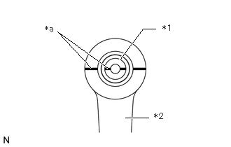
| *1 | Cross Shaft |
| *2 | Pitman Arm |
| *a | Matchmark |
Align the matchmarks on the pitman arm and cross shaft.
Install the pitman arm to the cross shaft with the spring washer and nut.
- Torque:
- 195 N*m (1988 kgf*cm, 144 ft.*lbf)
45460A 8.INSTALL TIE ROD ASSEMBLY
Install the tie rod to the right and left knuckle arm, and then install the 2 castle nuts.
- Torque:
- 90.7 N*m (925 kgf*cm, 67 ft.*lbf)
Install the 2 new cotter pins.
45450 9.INSTALL STEERING RELAY ROD ASSEMBLY
Install the steering relay rod assembly to the pitman arm and knuckle arm, and then install the 2 castle nuts.
- Torque:
- 90.7 N*m (925 kgf*cm, 67 ft.*lbf)
Install the 2 new cotter pins.
Tighten the 2 bolts and 2 nuts to tighten the 2 clamps.
- Torque:
- 36.8 N*m (375 kgf*cm, 27 ft.*lbf)
45721 10.INSTALL STEERING DAMPER BRACKET
Install the steering damper bracket with the 3 bolts.
- Torque:
- 39 N*m (398 kgf*cm, 29 ft.*lbf)
45700 11.INSTALL STEERING DAMPER ASSEMBLY
Install the steering damper assembly to the steering relay rod end sub-assembly and steering damper bracket, and then install the 2 nuts.
- Torque:
- 73.6 N*m (751 kgf*cm, 54 ft.*lbf)
12.INSTALL FRONT WHEELS
13.INSPECT AND ADJUST FRONT WHEEL ALIGNMENT