1VD-FTV EMISSION CONTROL VACUUM SWITCHING VALVE(for DPF) ON-VEHICLE INSPECTION
CAUTION / NOTICE / HINT
- NOTICE:
-
Always stop the engine when installing or removing the vacuum pump, or when removing the vacuum hoses.
PROCEDURE

 25860 1.CHECK NO. 1 VACUUM SWITCHING VALVE OPERATION (for EGR Cooler Bypass Valve)
Remove the vacuum hose of the No. 1 vacuum switching valve from the EGR cooler.
Using a 3-way connector, connect a vacuum pump to the hose between the No. 2 EGR valve assembly and No. 1 vacuum switching valve assembly.
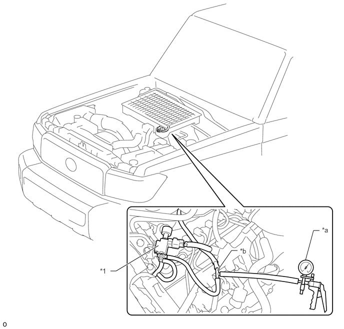
| *1 | No. 1 Vacuum Switching Valve Assembly | - | - |
| *a | Vacuum Pump | *b | 3-way Connector |
Connect the GTS to the DLC3.
Start the engine and turn the GTS on.
Warm up the engine (engine coolant temperature reaches 75°C (167°F) or higher), and make sure the A/C switch and all accessory switches are off.
Enter the following menus: Powertrain / Engine and ECT / Active Test / Activate the VSV for EGR Cooler Bypass / Data List / EGR Cooler Bypass Position.
- Powertrain > Engine and ECT > Active Test
-
Active Test Display Activate the VSV for EGR Cooler Bypass -
Data List Display EGR Cooler Bypass Position - 50004 61 181 728
Using the Active Test function, switch the EGR valve bypass switching valve between "Cooler" and "Bypass" a few times, and then check for changes in negative pressure.
- OK:
-
EGR Cooler Bypass Position Result Cooler ←→ Bypass -100 kPa (-1.0 kgf/cm2, -15 psi) ←→ 0 kPa
- HINT:
-
If the result is not as specified, perform an inspection on the vacuum hose for air leaks and inspect the No. 1 vacuum switching valve assembly.
25860 2.INSPECT NO. 1 VACUUM SWITCHING VALVE ASSEMBLY (for EGR Cooler Bypass Valve)
Measure the resistance according to the value(s) in the table below.
- Standard Resistance:
-
Tester Connection Condition Specified Condition 1 - 2 20°C (68°F) 37 to 44 Ω 1 - Body ground
2 - Body ground20°C (68°F) 10 kΩ or higher
If the result is not as specified, replace the No. 1 vacuum switching valve assembly.
Check operation of the No. 1 vacuum switching valve assembly.
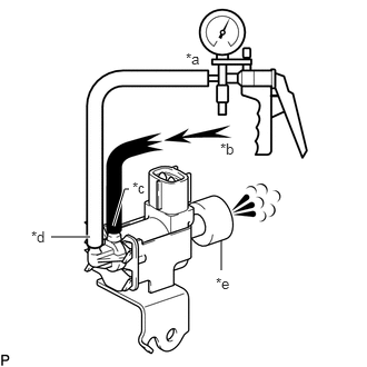
| *a | Vacuum |
| *b | Air |
| *c | Port E |
| *d | Port F |
| *e | Filter |
When a vacuum of 67 kPa (500 mmHg, 19.7 in.Hg) is applied to port F, check that air flows from port E to the filter.
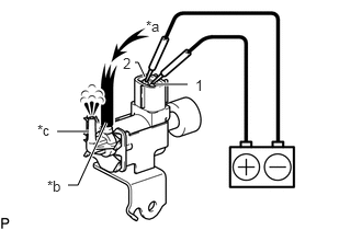
| *a | Air |
| *b | Port E |
| *c | Port F |
Apply battery voltage across terminals 1 and 2.
Check that air flows from port E to port F.
If the result is not as specified, replace the No. 1 vacuum switching valve assembly.