BRAKE CONTROL / DYNAMIC CONTROL SYSTEMS ANTI-LOCK BRAKE SYSTEM Brake Warning Light Remains ON
DESCRIPTION
When one of the following conditions is met, the brake warning light remains on:
The brake fluid level is insufficient.
The vacuum inside the brake booster decreases (for 1HZ and 1VD-FTV).
The brake warning light circuit is shorted.
WIRING DIAGRAM
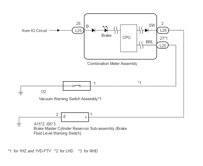
CAUTION / NOTICE / HINT
- NOTICE:
-
·
for 1HZ and 1VD-FTV:
If there is a brake booster system malfunction, such as a problem with the response of the brake pedal when it is depressed, inspect the brake booster system first.
Brake booster inspection: Click hereBrake>BRAKE SYSTEM (OTHER)>BRAKE BOOSTER>ON-VEHICLE INSPECTION
Vacuum pump inspection: Click hereBrake>BRAKE SYSTEM (OTHER)>VACUUM PUMP(for 1HZ)>ON-VEHICLE INSPECTION for 1HZ, Click hereBrake>BRAKE SYSTEM (OTHER)>VACUUM PUMP(for 1VD-FTV)>ON-VEHICLE INSPECTION for 1VD-FTV
·Before disconnecting the connector, make sure that there are no problems with the connection.
·After disconnecting the connector, make sure that the connector case and terminals are not deformed or corroded.
PROCEDURE
Turn the ignition switch to ON.
With the brake fluid at the specified level, disconnect the A15*1 or I85*2 brake master cylinder reservoir sub-assembly (brake fluid level warning switch) connector and check the brake warning light.
*1: for LHD
*2: for RHD
- Result:
-
Result Proceed to Brake warning light does not turn off (for 1HZ and 1VD-FTV) A Brake warning light does not turn off (except 1HZ and 1VD-FTV) B Brake warning light turns off C
- HINT:
-
If the brake warning light turns off, the brake master cylinder reservoir sub-assembly (brake fluid level warning switch) has an internal short circuit.
A
B
C
Start the engine.
Idle the engine.
Disconnect the I32 vacuum warning switch connector and check the brake warning light.
- Result:
-
Proceed to Brake warning light does not turn off Brake warning light turns off
- HINT:
-
If the brake warning light turns off, the vacuum warning switch has an internal short circuit.
Brake warning light does not turn off
Brake warning light turns off
Turn the ignition switch off.
Disconnect the L26 combination meter assembly connector.
for 1HZ and 1VD-FTV:
Disconnect the L25 combination meter assembly connector.
Measure the resistance according to the value(s) in the table below.
- Standard Resistance:
-
Tester Connection Condition Specified Condition L26-2 (SW) or A15-1 (+)*1 or I85-1 (+)*2 - Body ground Always 10 kΩ or higher L25-27 (BRL)*3 or I32-1*3 - Body ground Always 10 kΩ or higher
*1: for LHD
*2: for RHD
*3: for 1HZ and 1VD-FTV
- Result:
-
Proceed to OK NG
OK
Click hereVehicle Interior>METER / GAUGE / DISPLAY>METER / GAUGE SYSTEM>HOW TO PROCEED WITH TROUBLESHOOTING
NG