H150F MANUAL TRANSMISSION / TRANSAXLE MANUAL TRANSMISSION UNIT INSPECTION
PROCEDURE

 33331 1.INSPECT REVERSE GEAR
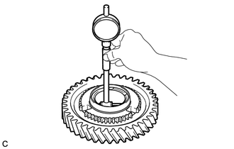
Using a cylinder gauge, measure the inside diameter of the reverse gear.
- Standard inside diameter:
-
51.515 to 51.540 mm (2.0281 to 2.0291 in.)
- Maximum inside diameter:
-
51.540 mm (2.0291 in.)
- HINT:
-
If the inside diameter is more than the maximum, replace the reverse gear with a new one.
2.INSPECT REVERSE GEAR THRUST CLEARANCE
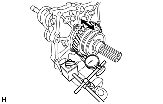
Using a dial indicator, measure the reverse gear thrust clearance.
- Standard clearance:
-
0.15 to 0.52 mm (0.0059 to 0.0205 in.)
- Maximum clearance:
-
0.52 mm (0.0205 in.)
- HINT:
-
If the clearance is not as specified, replace the reverse gear, No. 4 transmission clutch hub and counter shaft center bearing.
3.INSPECT REVERSE GEAR RADIAL CLEARANCE
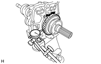
Using a dial indicator, measure the reverse gear radial clearance.
- Standard clearance:
-
0.015 to 0.068 mm (0.00060 to 0.00267 in.)
- Maximum clearance:
-
0.068 mm (0.00267 in.)
- HINT:
-
If the clearance is not as specified, replace the reverse gear, reverse gear bearing and output shaft.
33461 4.INSPECT REVERSE IDLER GEAR
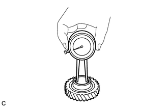
Using a caliper gauge, measure the inside diameter of the reverse idler gear.
- Standard inside diameter:
-
35.015 to 35.036 mm (1.3786 to 1.3793 in.)
- Maximum inside diameter:
-
35.036 mm (1.3793 in.)
- HINT:
-
If the inside diameter is more than the maximum, replace the reverse idler gear with a new one.
5.INSPECT REVERSE IDLER GEAR RADIAL CLEARANCE
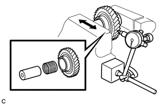
Install the reverse idler gear and reverse idler gear bush or bearing to the reverse idler gear shaft, and clamp it in a vise between aluminum plates.
- NOTICE:
-
Do not overtighten the vise.
Using a dial indicator, measure the reverse gear idler gear radial clearance.
- Standard clearance:
-
0.015 to 0.059 mm (0.00060 to 0.00232 in.)
- HINT:
-
If the inside diameter is more than the maximum, replace the reverse idler gear, reverse idler gear bush or bearing and reverse idler gear shaft with a new one.
33451 6.INSPECT REVERSE IDLER GEAR SHAFT
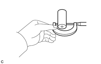
Using a micrometer, measure the outside diameter of the reverse idler gear shaft.
- Standard outside diameter:
-
27.987 to 28.000 mm (1.1019 to 1.1023 in.)
- Minimum diameter:
-
27.987 mm (1.1019 in.)
- HINT:
-
If the outside diameter is less than the minimum, replace the reverse idler gear shaft with a new one.
33049 7.INSPECT REVERSE SYNCHRONIZER RING SET
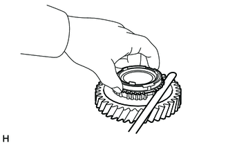
Measure the clearance between the reverse synchronizer ring and reverse gear while pushing the reverse synchronizer ring against the cone of the reverse gear.
- Standard clearance:
-
1.045 to 1.805 mm (0.0411 to 0.0711 in.)
- Maximum clearance:
-
1.805 mm (0.0711 in.)
- NOTICE:
-
Make sure to perform the measurement along the entire circumference of the reverse gear.
- HINT:
-
If the clearance is not as specified, replace the reverse synchronizer ring set with a new one.
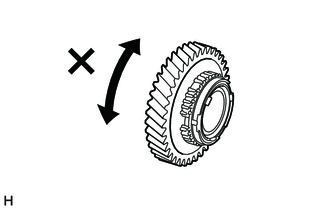
Apply gear oil to the cone of the reverse gear, and check that it does not turn in either direction while pushing the reverse synchronizer ring set.
- HINT:
-
If it turns, replace the reverse synchronizer ring set.
33368 8.INSPECT NO. 2 SYNCHRONIZER RING
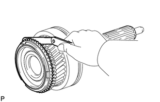
Push the No. 2 synchronizer ring against the cone of the input shaft. Measure the clearance between the No. 2 synchronizer ring and input shaft.
- Standard clearance:
-
0.75 to 1.65 mm (0.0295 to 0.0650 in.)
- Minimum clearance:
-
0.75 mm (0.0295 in.)
- NOTICE:
-
Make sure to perform the measurement along the entire circumference of the input shaft.
- HINT:
-
If the clearance is not as specified, replace the No. 2 synchronizer ring with a new one.
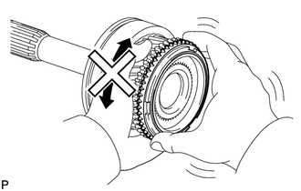
Apply gear oil to the cone of the input shaft, and check that it does not turn in either direction while pushing the No. 2 synchronizer ring.
- HINT:
-
If it turns, replace the No. 2 synchronizer ring.
33211 9.INSPECT REVERSE SHIFT FORK
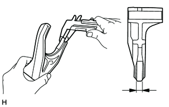
Using a vernier caliper, measure the thickness of the claw part of the reverse shift fork.
- Standard thickness:
-
11.75 to 11.85 mm (0.463 to 0.467 in.)
- Minimum thickness:
-
11.75 mm (0.463 in.)
- HINT:
-
If the thickness of the claw part is less than the minimum, replace the reverse shift fork with a new one.
33212A 10.INSPECT NO. 1 GEAR SHIFT FORK
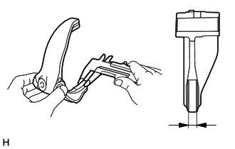
Using a vernier caliper, measure the thickness of the claw part of the No. 1 gear shift fork.
- Standard thickness:
-
11.75 to 11.85 mm (0.463 to 0.467 in.)
- Minimum thickness:
-
11.75 mm (0.463 in.)
- HINT:
-
If the thickness of the claw part is less than the minimum, replace the No. 1 gear shift fork with a new one.
33213G 11.INSPECT NO. 2 GEAR SHIFT FORK
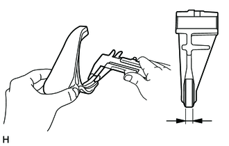
Using a vernier caliper, measure the thickness of the claw part of the No. 2 gear shift fork.
- Standard thickness:
-
11.75 to 11.85 mm (0.463 to 0.467 in.)
- Minimum thickness:
-
11.75 mm (0.463 in.)
- HINT:
-
If the thickness of the claw part is less than the minimum, replace the No. 2 gear shift fork with a new one.
33214G 12.INSPECT NO. 3 GEAR SHIFT FORK
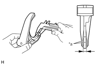
| *a | Pad |
Using a vernier caliper, measure the thickness of the claw part of the No. 3 gear shift fork.
- Standard thickness:
-
9.76 to 10.24 mm (0.384 to 0.403 in.)
- Minimum thickness:
-
9.76 mm (0.384 in.)
- NOTICE:
-
Check the thickness including the pad.
- HINT:
-
If the measurement result is less than the minimum and the pad is damaged, replace the No. 3 gearshift fork with a new one.
33327 13.INSPECT NO. 4 TRANSMISSION HUB SLEEVE
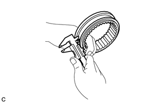
Using a vernier caliper, measure the No. 4 transmission hub sleeve groove.
- Standard groove:
-
12.0 to 12.1 mm (0.472 to 0.476 in.)
- Maximum groove:
-
12.1 mm (0.476 in.)
- HINT:
-
If the measurement result is more than the maximum, replace the No. 4 transmission hub sleeve with a new one.
14.INSPECT OIL PUMP RELIEF VALVE
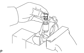
Coat the oil pump relief valve with gear oil, and then check that it falls smoothly into the valve hole by its own weight.
- HINT:
-
If the relief valve does not, replace it. If necessary, replace the oil pump cover assembly.
15.INSPECT OIL PUMP ROTOR SET
Install the oil pump drive rotor and transmission oil pump driven rotor to the oil pump cover assembly. Check that the rotors revolve smoothly.
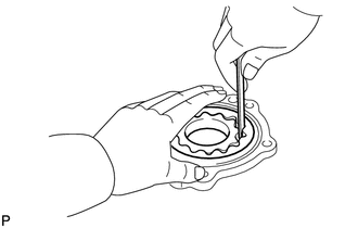
Using a feeler gauge, measure the clearance between the drive and driven rotor tips, as shown in the illustration.
- Standard Tip Clearance:
-
0.10 to 0.22 mm (0.00394 to 0.00866 in.)
- Maximum Tip Clearance:
-
0.22 mm (0.00866 in.)
- HINT:
-
If the clearance exceeds the maximum, replace the transmission oil pump drive rotor or transmission oil pump driven rotor with a new one.
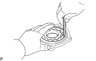
Using a feeler gauge, measure the clearance between the transmission oil pump cover and transmission oil pump driven rotor, as shown in the illustration.
- Standard body clearance:
-
0.075 to 0.170 mm (0.00296 to 0.00669 in.)
- Maximum body clearance:
-
0.170 mm (0.00669 in.)
- HINT:
-
If the clearance exceeds the maximum, replace the transmission oil pump driven rotor or transmission oil pump cover with a new one.