NETWORKING CAN COMMUNICATION SYSTEM(for RHD with VSC) DTC COMBINATION TABLE
HOW TO INTERPRET COMMUNICATION DTCS (DTCS THAT START WITH U)
If a CAN communication error cannot be reproduced, determine the suspected malfunctioning part using the DTCs stored in ECUs that are connected to the CAN buses by following the procedure below.
- HINT:
-
Communication DTCs (DTCs that start with U) indicate a communication error between the ECU that stores the DTC and the ECU that is indicated by the DTC.
If multiple ECUs store a communication DTC for a particular ECU, a communication stop of the ECU is suspected.
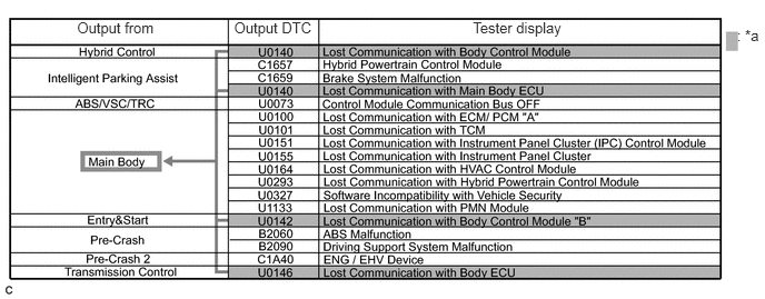
| *a | Items to be Checked | - | - |
- NOTICE:
-
·
This DTC table is from another model, and is only used here to show an example of DTCs that are output when there is an open in a CAN branch line for the main body ECU. This table does not show DTCs applicable to this vehicle.
·Even though a DTC title may indicate a communication error with a specific ECU, the ECU name used in the DTC name on the GTS may differ depending on the ECU that stores the DTC. (Regarding output DTCs, refer to DTC Table by ECU.)
- HINT:
-
As multiple ECUs indicate a communication stop with the main body ECU, the possibility of a communication stop of the main body ECU is high.
If almost all of the communication DTCs of an ECU are stored, a communication stop of the ECU is suspected.
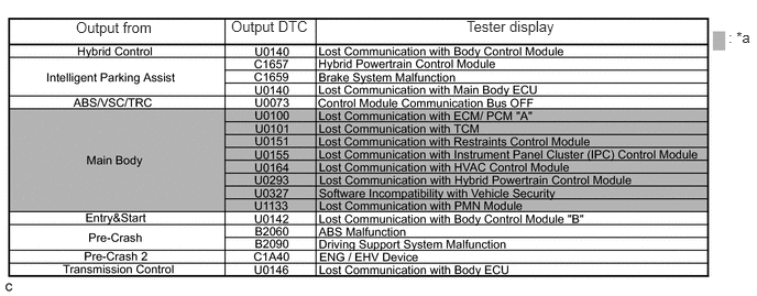
| *a | Items to be Checked | - | - |
- NOTICE:
-
·
This DTC table is from another model, and is only used here to show an example of DTCs that are output when there is an open in a CAN branch line for the main body ECU. This table does not show DTCs applicable to this vehicle.
·Even though a DTC title may indicate a communication error with a specific ECU, the ECU name used in the DTC name on the GTS may differ depending on the ECU that stores the DTC. (Regarding output DTCs, refer to DTC Table by ECU.)
- HINT:
-
·
If almost all of the DTCs of the main body ECU are stored, the possibility of a communication stop of the main body ECU is high.
·When a CAN communication error occurs, many DTCs are output. DTCs other than communication error DTCs (such as DTCs that start with C or B) and communication DTCs for the ABS system are important DTCs, however it may be easier to determine the malfunctioning part by examining the overall situation without considering these DTCs.
To help determine the part of the sub bus that has a communication error, prioritize the communication stop DTCs stored in the gateway function equipped ECU.
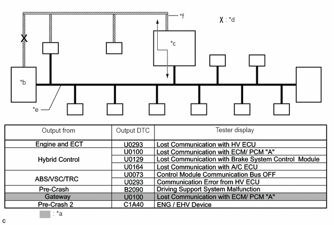
| *a | Items to be Checked | *b | ECM |
| *c | Gateway function equipped ECU | *d | Location of malfunction |
| *e | Central bus | *f | Sub bus |
- NOTICE:
-
This DTC table is from another model, and is only used here to show the ECUs connected to both a central bus and a sub bus. It shows DTCs output when there is an open in the main bus lines for the ECM on the sub bus. This table does not show DTCs applicable to this vehicle.
- HINT:
-
·
As gateway function equipped ECUs (sub bus monitor ECU) monitor signals from all ECUs that are connected to sub buses, gateway function equipped ECUs can detect ECUs with a communication stop more accurately.
·When there is a communication stop for the gateway function equipped ECU (gateway), communication with ECUs connected to other buses such as the central bus stops. Therefore, communication DTCs for ECUs connected to other buses are also stored.
When any of the following malfunctions occurs, many DTCs are likely to be output from many ECUs. Because of this, it may be difficult to determine the probable malfunctioning part.
Short between CAN lines (CANH and CANL)
Short between a CAN line (CANH or CANL) and ground
Short between a CAN line (CANH or CANL) and +B
Open in a CAN branch line (CANH or CANL) of an ECU or sensor
Open in a CAN main bus line (CANH or CANL) between 2 ECUs that have a terminating resistor
DTC COMBINATION TABLE (OPEN IN CAN BRANCH OF V BUS, PAST COMMUNICATION ERROR)
Regarding the past communication error of ECUs and sensors connected to the V bus (in this case, normal was displayed when performing the CAN bus check, but communication DTCs are output), the probable CAN branch that had a malfunction can be determined based on the following DTC combination table.
- HINT:
-
·
Based on the table below and DTCs output from ECUs connected via CAN communication, the probable part for which communication stop occurred can be determined.
·Regarding an open in a CAN branch and a communication stop that is currently occurring, the malfunctioning part can be confirmed easily by performing the CAN bus check using the GTS because the ECU or sensor connected to the CAN branch does not respond (the ECU or sensor name will not be displayed on the screen).
·If an open in a CAN main bus wire, a short between the CAN bus lines (CANH and CANL) or a +B or ground short in the CAN bus occurs, DTCs of almost all ECUs (or sensors) on the CAN bus may be output, or a message indicating a communication error may be displayed on the GTS screen. In this case, check the resistance of the CAN bus (steps 7 to 9) first.
·If an open occurs in just one of the lines of a CAN branch, DTCs which are not related to malfunctioning parts may be output (DTCs may be displayed randomly), or a message indicating a communication error may be displayed.
·○: DTC is output.
·-: DTC is not output.
·*: DTC U0073 may be stored when communication is lost.
| Output from | Output DTC | Trouble Mode | |||
|---|---|---|---|---|---|
| V Bus | |||||
| Skid Control ECU Communication Stop Mode (  ) |
Steering Angle Sensor Communication Stop Mode ( ) |
Center Airbag Sensor Communication Stop Mode ( ) |
DLC3 | ||
| Brake Actuator Assembly (Skid Control ECU)* | U0100 | ○ | - | - | - |
| U0124 | ○ | - | ○ | - | |
| U0126 | ○ | ○ | - | - | |
| Combination Meter Assembly | U0100 | - | - | - | - |
| U0129 | ○ | - | - | - | |
| U0151 | - | - | ○ | - | |
| ECM | - | - | - | - | - |
| Spiral with Sensor Cable Sub-assembly (Steering Angle Sensor) | - | - | - | - | - |
| Airbag Sensor Assembly | - | - | - | - | - |
| Output from | Output DTC | Trouble Mode | |
|---|---|---|---|
| V Bus | |||
| ECM Communication Stop Mode ( ) |
Combination Meter ECU Communication Stop Mode ( ) |
||
| Brake Actuator Assembly (Skid Control ECU)* | U0100 | ○ | - |
| U0124 | - | - | |
| U0126 | - | - | |
| Combination Meter Assembly | U0100 | ○ | ○ |
| U0129 | - | ○ | |
| U0151 | - | ○ | |
| ECM | - | - | - |
| Spiral with Sensor Cable Sub-assembly (Steering Angle Sensor) | - | - | - |
| Airbag Sensor Assembly | - | - | - |
| Output from | Output DTC | Trouble Mode |
|---|---|---|
| V Bus | ||
| CANH - CANL CANH - GND CANL - GND |
||
| Brake Actuator Assembly (Skid Control ECU)* | U0100 | ○ |
| U0124 | ○ | |
| U0126 | ○ | |
| Combination Meter Assembly | U0100 | ○ |
| U0129 | ○ | |
| U0151 | ○ | |
| ECM | - | - |
| Spiral with Sensor Cable Sub-assembly (Steering Angle Sensor) | - | - |
| Airbag Sensor Assembly | - | - |