BRAKE SYSTEM (OTHER) LOAD SENSING PROPORTIONING VALVE ON-VEHICLE INSPECTION
PROCEDURE

 47900 1.CHECK LOAD SENSING PROPORTIONING VALVE ASSEMBLY
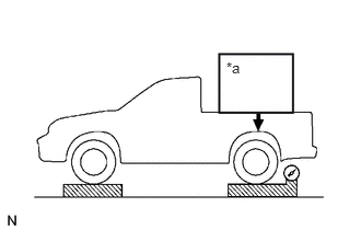
| *a | Weight |
Set the vehicle to its curb weight.
Place weights (as necessary) on the rear deck until the rear axle load is as shown below.
- Standard Rear Axle Load:
-
Vehicle Type Specified Condition GRJ71 12258 N (1250 kgf, 2755.7 lbf) GRJ76 12258 N (1250 kgf, 2755.7 lbf) GRJ78 14710 N (1500 kgf, 3306.9 lbf) GRJ79 14710 N (1500 kgf, 3306.9 lbf) HZJ71 12258 N (1250 kgf, 2755.7 lbf) HZJ76 12258 N (1250 kgf, 2755.7 lbf) HZJ78 14710 N (1500 kgf, 3306.9 lbf) HZJ79 14710 N (1500 kgf, 3306.9 lbf) VDJ76 12258 N (1250 kgf, 2755.7 lbf) VDJ79 14710 N (1500 kgf, 3306.9 lbf)
- NOTICE:
-
·
Be sure that the vehicle is on a level surface before starting the procedure.
·When placing the weights on the vehicle, first place the weights so that the total is approximately 60 kg (132 lb) more than the specification. Then remove weights as necessary to adjust the load.
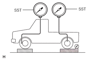
Install SST and bleed air from the brake system.
- SST
-
09709-29018
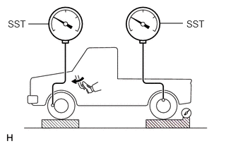
Raise the front brake fluid pressure to 9000 kPa (91.8 kgf/cm2, 1305 psi) by depressing the brake pedal, and measure the rear brake fluid pressure.
- Standard Rear Brake Fluid Pressure:
-
5082 to 6258 kPa (51.9 to 63.8 kgf/cm2, 737 to 907 psi)
- HINT:
-
The pedal should not be depressed twice or released while the specified pressure is being set. Read the value of the rear pressure after adjusting and holding the specified fluid pressure for 2 seconds.
If necessary, adjust the load sensing proportioning valve.
47900 2.ADJUST LOAD SENSING PROPORTIONING VALVE ASSEMBLY
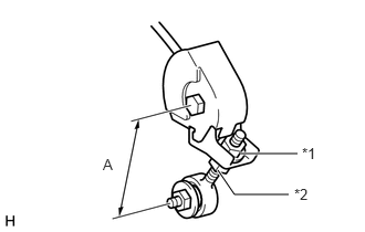
| *1 | Lock Nut |
| *2 | Adjusting Nut |
Adjust the length of the No. 2 load sensing spring shackle.
Loosen the lock nut, and then adjust the length of the No. 2 shackle.
When the rear brake fluid pressure is below the standard pressure, lengthen length A.
When the rear brake fluid pressure is higher than the standard pressure, shorten length A.
- Standard Initial Length (A):
-
78 mm (3.07 in.)
- Standard Length (A) after Adjustment:
-
72 to 84 mm (2.84 to 3.30 in.)
- HINT:
-
The rear fluid pressure changes according to the table below by turning the adjusting nut.
- Standard Rear Brake Fluid Pressure:
- For 1 Turn of Lock Nut:
-
187 kPa (1.9 kgf/cm2, 27 psi)
Tighten the adjusting nut and lock nut.
- Torque:
- 24.5 N*m (250 kgf*cm, 18 ft.*lbf)
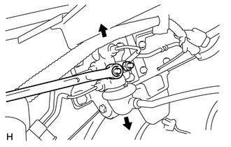
If the pressure cannot be adjusted by the No. 2 shackle, raise or lower the valve body.
When the pressure is below the standard pressure, lower the load sensing valve assembly.
When the pressure is higher than the standard pressure, raise the load sensing valve assembly.
Tighten the 2 nuts.
- Torque:
- 12.5 N*m (127 kgf*cm, 9 ft.*lbf)
Adjust the length of the No. 2 shackle again. If the rear fluid pressure cannot be adjusted, check the valve body.
3.CHECK VALVE BODY
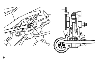
Install the valve body in the uppermost position.
- HINT:
-
When the brakes are applied, the position will move down by approximately 0.8 mm (0.0315 in.). Even at this time, the piston should not make contact with or move the load sensing spring.
If the result is not as specified, replace the load sensing valve assembly.
Using SST, check the rear brake pressure.
- SST
-
09709-29018
- Standard Pressure:
-
Front Brake Pressure Rear Brake Pressure 981 kPa (10.0 kgf/cm2, 142 psi) 981 kPa (10.0 kgf/cm2, 142 psi) 4903 kPa (50.0 kgf/cm2, 711 psi) 1569 to 2354 kPa (16.0 to 24.0 kgf/cm2, 228 to 341 psi) 9807 kPa (100.0 kgf/cm2, 1422 psi) 2697 to 3677 kPa (27.5 to 37.5 kgf/cm2, 391 to 533 psi)
If the result is not as specified, replace the load sensing proportioning valve.