RM25T0E _58 Vehicle Interior _029924 DOOR LOCK _0137600 DOOR CONTROL RELAY G
DOOR LOCK DOOR CONTROL RELAY ON-VEHICLE INSPECTION
PROCEDURE

 85980 1.INSPECT DOOR CONTROL RELAY ASSEMBLY
a.
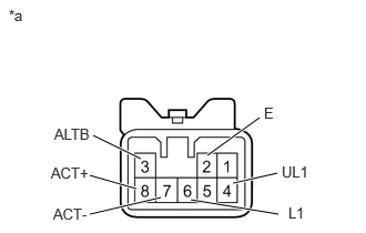
1.948,1.458 2.438,1.104 true 1.792,1.875 2.615,2.01 true 1.51,1.854 0.844,2.01 true 1.281,1.771 0.844,1.646 true 1.323,1.49 0.875,1.271 true 2.188,1.719 2.604,1.625 true 0.083,0.063 2.354,0.406 2.271,0.344 10 false *a 0.51,1.177 1.125,1.375 0.615,0.198 10 false ALTB 0.479,1.542 0.885,1.74 0.406,0.198 10 false ACT+ 0.5,1.927 0.958,2.125 0.458,0.198 10 false ACT- 2.479,0.979 3.094,1.177 0.615,0.198 10 false E 2.708,1.917 3.021,2.115 0.313,0.198 10 false L1 2.646,1.531 3.115,1.729 0.469,0.198 10 false UL1
| *a | Component with harness connected (Door Control Relay Assembly) |
Check the voltage of the door control relay assembly.
i.
Measure the voltage according to the value(s) in the table below.
- Standard Voltage:
-
Tester Connection Terminal Description Condition Specified Condition 3 (ALTB) - 2 (E) +B power supply Always 11 to 14 V 8 (ACT+) - 2 (E) Door lock motor LOCK drive output Door lock control switch*1 (power window master switch*2) or driver side door key cylinder LOCK position Momentary output 11 to 14 V 7 (ACT-) - 2 (E) Door lock motor UNLOCK drive output Door lock control switch*1 (power window master switch*2) or driver side door key cylinder UNLOCK position 6 (L1) - 2 (E) Door lock control input Off 11 to 14 V Door lock control switch *1 (power window master switch *2) or driver side door key cylinder LOCK position Below 1 V 4 (UL1) - 2 (E) Door lock control input Off 11 to 14 V Door lock control switch *1 (power window master switch *2) or driver side door key cylinder Unlock position Below 1 V
- HINT:
-
·
*1: w/o Power Window
·*2: w/ Power Window
If the result is not as specified, replace the door control relay assembly.