DOOR LOCK POWER DOOR LOCK CONTROL SYSTEM TERMINALS OF ECU
CHECK DOOR CONTROL RELAY ASSEMBLY (w/o Wireless Door Lock Control System)
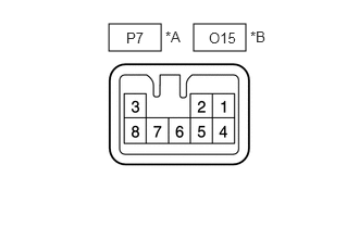
| *A | for LHD |
| *B | for RHD |
Disconnect the P7*1 or O15*2 door control relay assembly connector.
*1: for LHD
*2: for RHD
Measure the resistance and voltage according to the value(s) in the table below.
| Terminal No. (Symbol) | Wiring Color | Terminal Description | Condition | Specified Condition |
|---|---|---|---|---|
| P7-3 (B) - Body ground*1 | L-R - Body ground | Battery power supply | Always | 11 to 14 V |
| O15-3 (B) - Body ground*2 | L-R - Body ground | Battery power supply | Always | 11 to 14 V |
| P7-2 (E) - Body ground*1 | W-B - Body ground | Ground | Always | Below 1 Ω |
| O15-2 (E) - Body ground*2 | W-B - Body ground | Ground | Always | Below 1 Ω |
*1: for LHD
*2: for RHD
Reconnect the P7*1 or O15*2 door control relay assembly connector.
Measure the voltage according to the value(s) in the table below.
| Terminal No. (Symbol) | Wiring Color | Terminal Description | Condition | Specified Condition |
|---|---|---|---|---|
| P7-8 (ACT+) - Body ground*1 | B - Body ground | Door lock motor lock drive output | Power window regulator master switch assembly*3, door control switch assembly*4 or door key cylinder off → on (lock) | Below 1 V → 11 to 14 V → Below 1 V |
| O15-8 (ACT+) - Body ground*2 | B - Body ground | Door lock motor lock drive output | Power window regulator master switch assembly*3, door control switch assembly*4 or door key cylinder off → on (lock) | Below 1 V → 11 to 14 V → Below 1 V |
| P7-7 (ACT-) - Body ground*1 | W - Body ground | Door lock motor unlock drive output | Power window regulator master switch assembly*3, door control switch assembly*4 or door key cylinder off → on (unlock) | Below 1 V → 11 to 14 V → Below 1 V |
| O15-7 (ACT-) - Body ground*2 | W - Body ground | Door lock motor unlock drive output | Power window regulator master switch assembly*3, door control switch assembly*4 or door key cylinder off → on (unlock) | Below 1 V → 11 to 14 V → Below 1 V |
| P7-6 (L1) - Body ground*1 | G-R - Body ground | Power window regulator master switch assembly*3, door control switch assembly*4 or door key-linked lock input |
·
Door key cylinder turned to neutral position → on (lock)
·
Power window regulator master switch assembly*3 or door control switch assembly*4 off → on (lock) |
11 to 14 V → Below 1 V |
| O15-6 (L1) - Body ground*2 | G-R - Body ground | Power window regulator master switch assembly*3, door control switch assembly*4 or door key-linked lock input |
·
Door key cylinder turned to neutral position → on (lock)
·
Power window regulator master switch assembly*3 or door control switch assembly*4 off → on (lock) |
11 to 14 V → Below 1 V |
| P7-4 (UL1) - Body ground*1 | R-W - Body ground | Power window regulator master switch assembly*3, door control switch assembly*4 or door key-linked unlock input |
·
Door key cylinder turned to neutral position → on (unlock)
·
Power window regulator master switch assembly*3 or door control switch assembly*4 off → on (unlock) |
11 to 14 V → Below 1 V |
| O15-4 (UL1) - Body ground*2 | R-W - Body ground | Power window regulator master switch assembly*3, door control switch assembly*4 or door key-linked unlock input |
·
Door key cylinder turned to neutral position → on (unlock)
·
Power window regulator master switch assembly*3 or door control switch assembly*4 off → on (unlock) |
11 to 14 V → Below 1 V |
*1: for LHD
*2: for RHD
*3: w/ Power Window Control System
*4: w/o Power Window Control System
CHECK DOOR CONTROL WITH RECEIVER ECU ASSEMBLY (w/ Wireless Door Lock Control System)
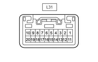
Disconnect the L31 door control with receiver ECU assembly connector.
Measure the resistance and voltage according to the value(s) in the table below.
| Terminal No. (Symbol) | Wiring Color | Terminal Description | Condition | Specified Condition |
|---|---|---|---|---|
| L31-1 (ALTB) - Body ground | L-R - Body ground | Battery power supply | Always | 11 to 14 V |
| L31-2 (B) - Body ground | R - Body ground | Battery power supply | Always | 11 to 14 V |
| L31-11 (E) - Body ground | W-B - Body ground | Ground | Always | Below 1 Ω |
Reconnect the L31 door control with receiver ECU assembly connector.
Measure the voltage according to the value(s) in the table below.
| Terminal No. (Symbol) | Wiring Color | Terminal Description | Condition | Specified Condition |
|---|---|---|---|---|
| L31-6 (UL1) - Body ground | W - Body ground | Power window regulator master switch assembly*1, door control switch assembly*2 or door key-linked unlock input |
·
Door key cylinder turned to neutral position → on (unlock)
·
Power window regulator master switch assembly*1 or door control switch assembly*2 off → on (unlock) |
11 to 14 V → Below 1 V |
| L31-7 (L1) - Body ground | R - Body ground*3 G - Body ground*4 |
Power window regulator master switch assembly*1, door control switch assembly*2 or door key-linked lock input |
·
Door key cylinder turned to neutral position → on (lock)
·
Power window regulator master switch assembly*1 or door control switch assembly*2 off → on (lock) |
11 to 14 V → Below 1 V |
| L31-10 (ACT-) - Body ground | W - Body ground | Door lock motor unlock drive output | Power window regulator master switch assembly*1, door control switch assembly*2 or door key cylinder off → on (unlock) | Below 1 V → 11 to 14 V → Below 1 V |
| L31-16 (LSWD) - Body ground | P - Body ground | Door unlock detection switch input | Driver side door unlock | Below 1 V |
| Driver side door lock | 11 to 14 V | |||
| L31-20 (ACT+) - Body ground | B-R - Body ground | Door lock motor lock drive output | Power window regulator master switch assembly*1, door control switch assembly*2 or door key cylinder off → on (lock) | Below 1 V → 11 to 14 V → Below 1 V |
*1: w/ Power Window Control System
*2: w/o Power Window Control System
*3: for LHD
*4: for RHD