SUPPLEMENTAL RESTRAINT SYSTEMS SPIRAL CABLE INSPECTION
PROCEDURE

 84306 1.INSPECT SPIRAL CABLE SUB-ASSEMBLY
- NOTICE:
-
As the spiral cable sub-assembly may break, do not rotate the spiral cable sub-assembly more than the specified amount.
Visually check for defects with the spiral cable sub-assembly.
The defects are as follows:
Scratches
Small cracks
Dents
Chips
Cracks or other damage to the connector
- OK:
-
No defects are found.
If any of the defects is found, replace the spiral cable sub-assembly with a new one.
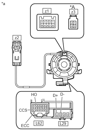
| *A | w/ Cruise Control System |
| *a | Component without harness connected (Spiral Cable Sub-assembly) |
Check the spiral cable.
Set the spiral cable sub-assembly to the center position.
Click hereVehicle Interior>SUPPLEMENTAL RESTRAINT SYSTEMS>SPIRAL CABLE>INSTALLATION
Measure the resistance between each terminal of the spiral cable sub-assembly according to the table below.
- Standard Resistance:
-
Tester Connection Condition Specified Condition L62-1 (CCS) - z3-3
*1Always 3 Ω or less L62-2 (ECC) - z3-4
*1L62-8 (HO) - z1-1 L29-1 (D+) - z2-2 L29-2 (D-) - z2-1
*1: w/ Cruise Control System
After setting the spiral cable sub-assembly to the center position, rotate the spiral cable sub-assembly 2.5 times clockwise, and measure the resistance as shown in the table below. Then rotate the spiral cable sub-assembly 5 times counterclockwise, and measure the resistance as shown in the table below.
- Standard Resistance:
-
Tester Connection Condition Specified Condition L62-1 (CCS) - z3-3
*1Always 3 Ω or less L62-2 (ECC) - z3-4
*1L62-8 (HO) - z1-1 L29-1 (D+) - z2-2 L29-2 (D-) - z2-1
*1: w/ Cruise Control System
After setting the spiral cable sub-assembly to the center position, rotate the spiral cable sub-assembly 2.5 times clockwise. Then while rotating the spiral cable sub-assembly 5 times counterclockwise, measure the resistance as shown in the table below.
- Standard Resistance:
-
Tester Connection Condition Specified Condition L62-1 (CCS) - z3-3
*1Always 3 Ω or less L62-2 (ECC) - z3-4
*1L62-8 (HO) - z1-1 L29-1 (D+) - z2-2 L29-2 (D-) - z2-1
*1: w/ Cruise Control System
If the result is not as specified, replace the spiral cable sub-assembly.