1VD-FTV INTAKE / EXHAUST INTERCOOLER INSTALLATION
PROCEDURE

 17940D 1.INSTALL INTERCOOLER ASSEMBLY
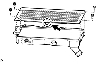
Install the intercooler protector to the intercooler assembly with the 4 bolts.
- Torque:
- 8.0 N*m (82 kgf*cm, 71 in.*lbf)
- HINT:
-
Install the intercooler protector with the protrusion facing towards the front of the vehicle.
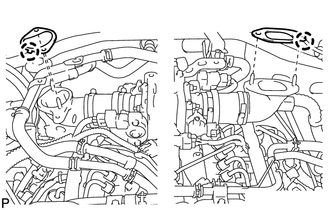
Install a new gasket to the No. 1 cool air inlet and a new gasket to the No. 2 cool air inlet.
- HINT:
-
Install the gaskets with the protrusions facing as shown in the illustration.
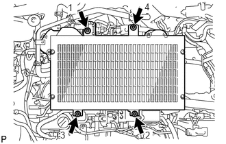
Temporarily install the intercooler assembly with the 2 bolts and 2 nuts. Then tighten the bolts and nuts in the order shown in the illustration.
- Torque:
- 21 N*m (214 kgf*cm, 15 ft.*lbf)
Install the No. 1 and No. 2 cool air inlets with the 4 nuts.
- Torque:
- 21 N*m (214 kgf*cm, 15 ft.*lbf)
Connect the intake air temperature sensor connector.
Connect the vacuum hose.
Connect the turbo pressure sensor connector.
17341F 2.INSTALL NO. 1 AIR HOSE
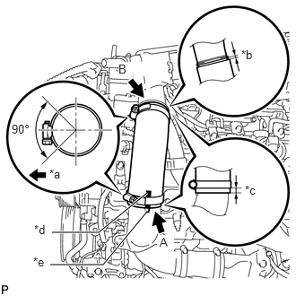
| *a | Front |
| *b | 0 to 3 mm |
| *c | 2 to 8 mm |
| *d | Marking |
| *e | Protrusion |
Install the No. 1 air hose with the 2 clamps.
- Torque:
- 6.3 N*m (64 kgf*cm, 56 in.*lbf)
- HINT:
-
·
Align the hose marking with the protrusion and install the hose.
·Push in part A of the No. 1 air hose until it contacts the stopper.
·Push in part B of the No. 1 air hose so that it is 0 to 3 mm (0 to 0.118 in.) from the stopper.
·Install the clamps as shown in the illustration.
·Install the clamps so that they are 2 to 8 mm (0.0787 to 0.315 in.) from the end of the hose.
87249B 3.CONNECT OUTLET HEATER WATER PIPE B
Connect the outlet heater water pipe B with the 2 bolts.
- Torque:
- 21 N*m (214 kgf*cm, 15 ft.*lbf)
4.CONNECT CABLE TO NEGATIVE BATTERY TERMINAL
5. INITIALIZATION AFTER RECONNECTING BATTERY TERMINAL
- HINT:
-
When disconnecting and reconnecting the battery, there is an automatic learning function that completes learning when the respective system is used.
-
Click hereGeneral>SETUP>WHEN DISCONNECTING OR RECONNECTING BATTERY TERMINAL>AUTOMATIC LEARNING CHART