ДВИГАТЕЛЬ В СБОРЕ > СНЯТИЕ |
| 1. DISCONNECT CABLE FROM NEGATIVE BATTERY TERMINAL |
| 2. REMOVE BATTERY HOLD DOWN CLAMP |
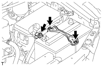 |
Remove the nut and disconnect the engine wire.
Remove the 2 nuts and battery hold down clamp.
| 3. REMOVE BATTERY |
| 4. REMOVE BATTERY TRAY |
| 5. REMOVE HOOD SUB-ASSEMBLY |
Disconnect the washer nozzle hose.
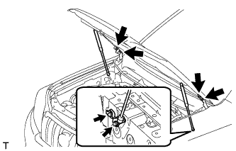 |
Remove the 8 bolts and hood.
| 6. REMOVE COWL TOP VENTILATOR LOUVER SUB-ASSEMBLY |
Remove the cowl top ventilator louver (See page Нажмите здесь).
| 7. REMOVE UPPER RADIATOR SUPPORT SEAL |
Освободите 13 фиксаторов и снимите верхнее уплотнение кронштейна радиатора.
| 8. REMOVE FRONT BUMPER COVER LOWER |
Remove the clip, 5 bolts and front bumper cover lower.
| 9. REMOVE NO. 1 ENGINE UNDER COVER SUB-ASSEMBLY |
Remove the 4 bolts.
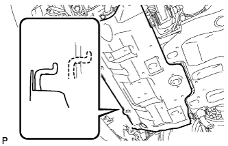 |
Unhook the engine under cover from the vehicle body as shown in the illustration.
| 10. REMOVE TRANSMISSION UNDER COVER |
Remove the 2 bolts and transmission under cover.
| 11. REMOVE REAR ENGINE UNDER COVER ASSEMBLY |
Remove the 4 bolts and rear engine under cover.
| 12. DRAIN ENGINE COOLANT |
Ослабьте пробку сливного крана радиатора.
| *1 | Пробка радиатора | *2 | Бачок радиатора |
| *3 | Пробка сливного крана радиатора | *4 | Пробка сливного крана блока цилиндров |
Слейте охлаждающую жидкость, сняв крышку радиатора.
Ослабьте пробку сливного крана блока цилиндров.
Ослабьте пробку сливного крана блока цилиндров и слейте охлаждающую жидкость из двигателя.
| 13. DRAIN ENGINE OIL |
Remove the oil filler cap.
Remove the oil drain plug and gasket, and then drain the oil into a container.
Clean the drain plug and install it with a new gasket.
| 14. REMOVE FRONT FENDER APRON SEAL RH |
Remove the 4 clips and fender apron seal.
| 15. REMOVE NO. 1 FRONT FENDER APRON TO FRAME SEAL RH |
Remove the 5 clips and frame seal.
| 16. REMOVE FRONT FENDER APRON SEAL LH |
Remove the 5 clips and fender apron seal.
| 17. REMOVE NO. 1 FRONT FENDER APRON TO FRAME SEAL LH |
Remove the 5 clips and frame seal.
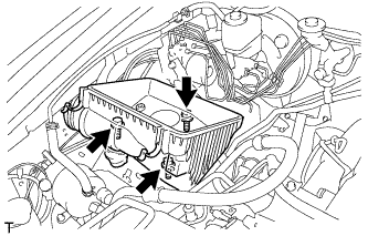
| 18. REMOVE RESONATOR WITH AIR CLEANER CAP SUB-ASSEMBLY |
 |
Disconnect the sensor connector.
Detach the wire harness clamp.
Loosen the hose clamp and remove the resonator with air cleaner cap.
 |
Detach the 4 hook clamps, and then remove the air cleaner cap and resonator with air cleaner cap.
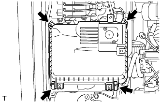
| 19. REMOVE AIR CLEANER FILTER ELEMENT SUB-ASSEMBLY |
| 20. REMOVE AIR CLEANER CASE ASSEMBLY |
 |
Remove the 3 bolts and air cleaner case.
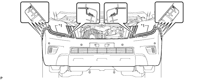
| 21. REMOVE FRONT BUMPER COVER |
Наклейте защитную ленту вокруг накладки переднего бампера.
Выверните 2 болта A и 2 болта B.
Выверните 6 винтов и освободите 6 фиксаторов.
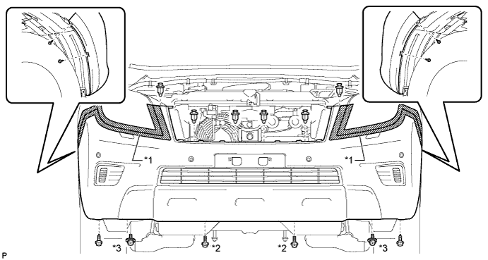
| *1 | Защитная клейкая лента | *2 | Болт A |
| *3 | Болт B | - | - |
Освободите 12 захватов.
Для моделей с сенсорной системой помощи при парковке TOYOTA и противотуманными фарами:
Отсоедините 3 разъема.
Для моделей с сенсорной системой помощи при парковке TOYOTA без противотуманных фар:
Отсоедините разъем.
Для моделей без сенсорной системы помощи при парковке TOYOTA и с противотуманными фарами:
Отсоедините 2 разъема.
Для моделей с системой очистителей фар:
Отсоедините шланг очистителя фар.
Снимите облицовку переднего бампера.
| *1 | Защитная клейкая лента | - | - |
| 22. REMOVE FRONT UPPER BUMPER RETAINER |
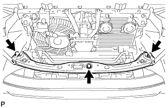 |
Remove the 3 bolts and retainer.
| 23. REMOVE RADIATOR SIDE DEFLECTOR LH |
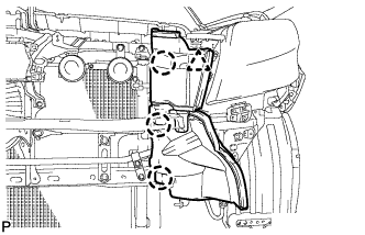 |
Using a clip remover, detach the 3 claws and remove the clip. Then move the side deflector so that the radiator can be removed in the step below.
| 24. REMOVE RADIATOR SIDE DEFLECTOR RH |
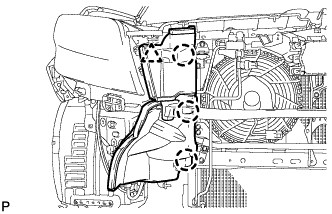 |
Using a clip remover, detach the 3 claws and remove the clip. Then move the side deflector so that the radiator can be removed in the step below.
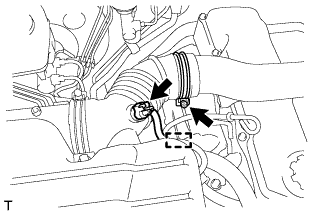
| 25. REMOVE NO. 1 RADIATOR HOSE |
 |
Detach the clamp and remove the No. 1 radiator hose.
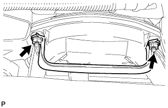 |
Remove the 2 nuts and hose clamp.
| 26. REMOVE NO. 2 RADIATOR HOSE |
 |
| 27. REMOVE FAN SHROUD |
 |
Loosen the 4 nuts holding the fluid coupling fan.
Remove the vane pump V belt and the fan and generator V belt (See page Нажмите здесь).
 |
Remove the 2 bolts holding the fan shroud.
Remove the 4 nuts of the fluid coupling fan, and then remove the shroud together with the coupling fan.
Remove the fan pulley from the water pump.
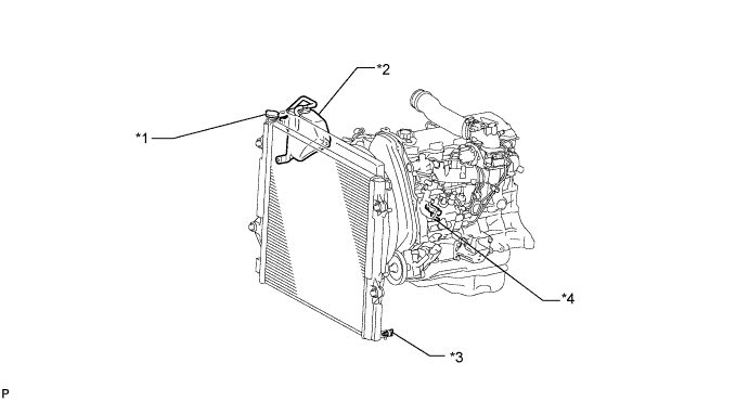
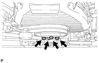
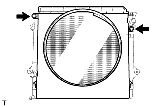
| 28. REMOVE RADIATOR ASSEMBLY |
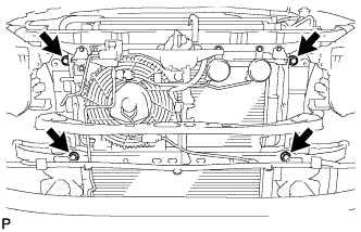 |
Remove the 4 bolts and radiator.
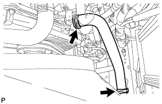
| 29. REMOVE INTAKE PIPE ASSEMBLY |
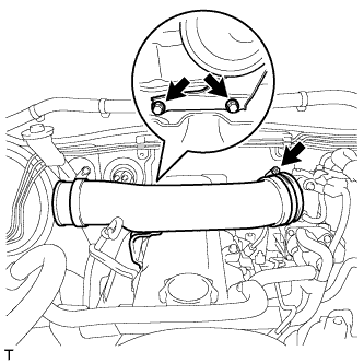 |
Loosen the hose clamp and remove the 2 bolts and intake pipe.
| 30. DISCONNECT COOLER COMPRESSOR ASSEMBLY |
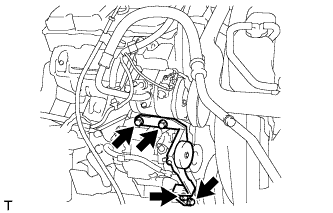 |
Remove the 4 bolts and idle pulley bracket.
 |
Disconnect the connector.
Remove the 3 bolts and disconnect the cooler compressor.
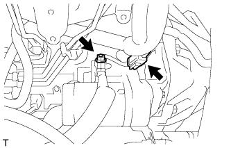
| 31. REMOVE GENERATOR ASSEMBLY |
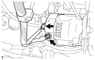 |
Remove the terminal cap.
Remove the nut and generator wire.
Disconnect the generator connector.
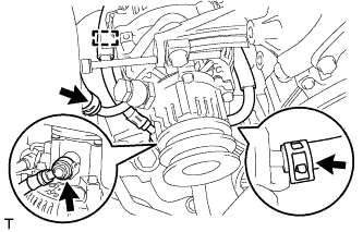 |
Disconnect the vacuum pump hose.
Remove the union bolt to disconnect the vacuum pump oil inlet hose and remove the 2 gaskets.
Detach the vacuum pump oil inlet hose from the cord clip.
Disconnect the vacuum pump oil outlet hose.
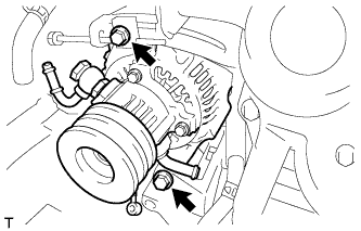 |
Remove the 2 bolts and generator.
| 32. REMOVE GLOVE COMPARTMENT DOOR ASSEMBLY |
Remove the glove compartment door (See page Нажмите здесь).
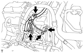
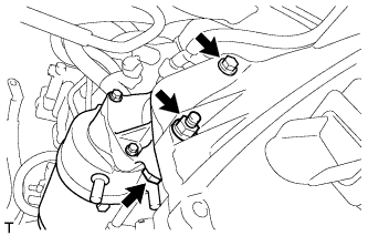
| 33. DISCONNECT ENGINE WIRE |
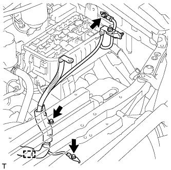 |
Remove the 3 bolts, detach the clamp and disconnect the engine wire.
Remove the No. 1 relay block cover.
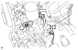 |
Remove the nut and detach the 2 claws.
Disconnect the connector.
Detach the 2 clamps and disconnect the engine wire.
 |
for LHD:
Detach the 4 clamps.
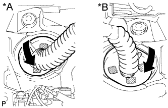 |
Detach the grommet from the wire harness support.
| *A | for LHD |
| *B | for RHD |
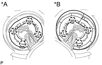 |
Detach the 4 claws to remove the wire harness support from the vehicle, and then pull out the ECM connector to remove it from the vehicle.
| *A | for LHD |
| *B | for RHD |
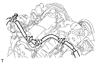
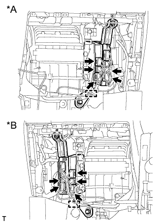 |
Detach the clamp and disconnect the 5 connectors as shown in the illustration.
| *A | for LHD |
| *B | for RHD |
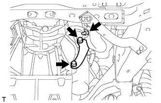
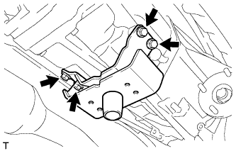
| 34. REMOVE WIRING HARNESS CLAMP BRACKET (for LHD) |
 |
Remove the bolt and wiring harness clamp bracket.
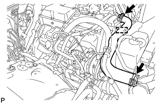
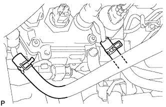
| 35. DISCONNECT HEATER WATER HOSE ASSEMBLY |
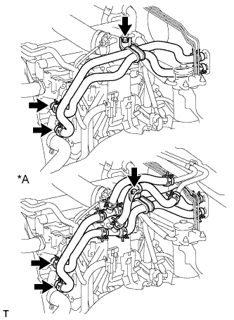 |
Remove the bolt and disconnect the heater water hoses.
| *A | for Rear Heater |
| 36. LOOSEN FUEL TANK CAP ASSEMBLY |
| 37. DRAIN FUEL |
 |
Loosen the fuel filter drain plug and drain the fuel from the fuel filter.
| 38. DISCONNECT FUEL HOSE |
 |
Disconnect the 2 fuel hoses.
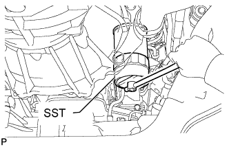
| 39. DISCONNECT VANE PUMP ASSEMBLY |
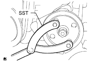 |
Using SST, hold the pulley and loosen the nut.
Remove the nut and vane pump pulley from the vane pump shaft.
Remove the 2 bolts and nut and disconnect the vane pump.
| 40. REMOVE CLUTCH RELEASE CYLINDER ASSEMBLY |
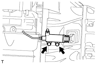 |
Remove the 2 bolts and disconnect the release cylinder.
| 41. REMOVE STARTER ASSEMBLY |
 |
Disconnect the starter connector.
Remove the terminal cap.
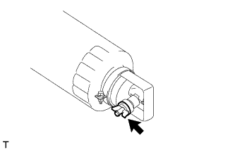
Remove the nut and disconnect the starter wire.
 |
Remove the nut, 2 bolts and starter.
| 42. REMOVE OIL FILTER SUB-ASSEMBLY |
 |
Using SST, remove the oil filter.
| 43. REMOVE FRONT EXHAUST PIPE ASSEMBLY |
Remove the bolt from the clamp.
 |
Remove the 2 bolts and No. 1 exhaust pipe support bracket.
 |
Remove the 3 nuts and front exhaust pipe.
Remove the gasket.
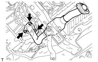
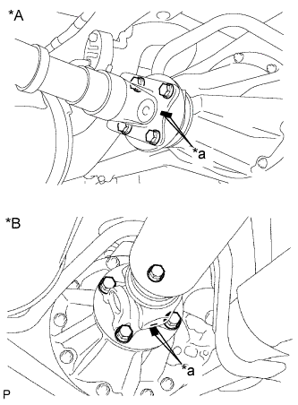
| 44. REMOVE FRONT PROPELLER SHAFT ASSEMBLY |
 |
Нанесите метки на фланец карданного вала и дифференциал.
| *a | Метка |
Снимите 4 гайки, 4 болта, 4 шайбы и передний карданный вал в сборе.
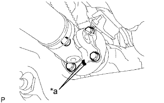
 |
Нанесите метки на фланец карданного вала и фланец раздаточной коробки.
| *a | Метка |
Отверните 4 гайки и снимите 4 шайбы и передний карданный вал в сборе.
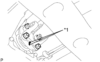
| 45. REMOVE PROPELLER SHAFT ASSEMBLY |
 |
Нанесите метки на фланец карданного вала и фланец раздаточной коробки.
| *A | Для 3-дверных моделей: |
| *B | Для 5-дверных моделей: |
| *a | Метка |
Отверните 4 гайки и снимите 4 шайбы.
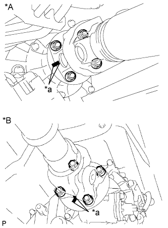
 |
Нанесите метки на фланец карданного вала и фланец дифференциала.
| *A | Для 3-дверных моделей: |
| *B | Для 5-дверных моделей: |
| *a | Метка |
Отверните 4 гайки и снимите 4 болта и 4 шайбы.
Снимите карданный вал.
| 46. REMOVE MANUAL TRANSMISSION ASSEMBLY |
Remove the manual transmission (See page Нажмите здесь).
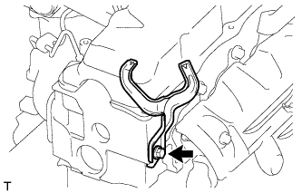
| 47. REMOVE REAR NO. 1 ENGINE MOUNTING INSULATOR |
 |
Remove the 4 bolts and rear engine mounting insulator from the transmission.
| 48. REMOVE CLUTCH COVER ASSEMBLY |
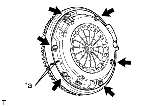 |
Place matchmarks on the clutch cover and flywheel.
| *a | Matchmark |
Loosen each set bolt one turn at a time until spring tension is released.
Remove the 6 set bolts and pull off the clutch cover.
| 49. REMOVE CLUTCH DISC ASSEMBLY |
| 50. REMOVE FLYWHEEL SUB-ASSEMBLY |
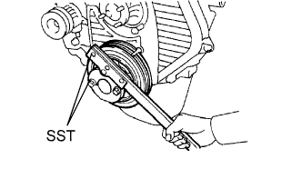 |
Using SST, hold the crankshaft.
Remove the 8 bolts and flywheel.
| 51. REMOVE REAR END PLATE |
Remove the 2 bolts and rear end plate.
| 52. REMOVE FLYWHEEL HOUSING DUST SEAL |
| 53. INSTALL ENGINE HANGER |
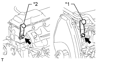 |
Install an engine hanger to each location shown in the illustration.
| *1 | No. 1 Engine Hanger |
| *2 | No. 2 Engine Hanger |
| No. 1 Engine Hanger | 12281-54080 |
| No. 2 Engine Hanger | 12282-54070 |
| Bolt (No. 1 Engine Hanger) | 90119-10736 |
| Bolt (No. 2 Engine Hanger) | 91622-61022 |
| 54. REMOVE ENGINE ASSEMBLY |
Attach an engine sling device and hang the engine with a chain block.
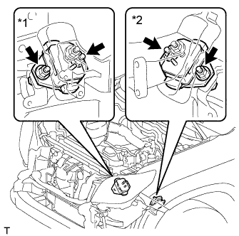 |
Remove the 4 nuts and 4 bolts from the front engine mounting insulator LH and RH.
| *1 | for RH Side |
| *2 | for LH Side |
Remove the engine by operating the engine sling device and chain block.
| 55. INSTALL ENGINE TO ENGINE STAND |
Install the engine to an engine stand with bolts.
Remove engine hanger.
| 56. REMOVE ENGINE WIRE |
Remove the engine wire from the engine.
| 57. REMOVE FRONT ENGINE MOUNTING INSULATOR |
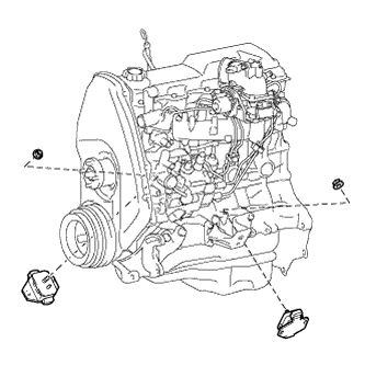 |
Remove the 2 nuts and 2 front engine mounting insulators.
