DTC 51 Stop Light Switch Circuit Malfunction |
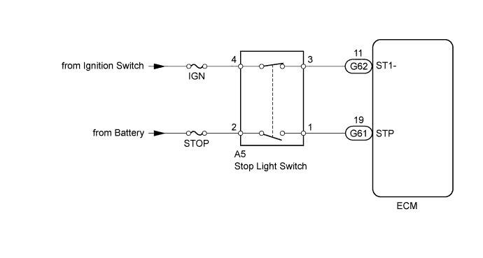
| Signal | Brake Pedal Released | In Transition | Brake Pedal Depressed |
| STP | Off | On | On |
| ST1- | On | On | Off |
| DTC No. | DTC Detection Condition | Trouble Area |
| 51 | Conditions (a), (b) and (c) continue for 0.5 seconds or more(1 trip detection logic): (a) Ignition switch is ON. (b) Brake pedal is released. (c) STP signal is off when ST1- signal is off. |
|
| 1.READ VALUE USING INTELLIGENT TESTER (STOP LIGHT SWITCH) |
Connect the intelligent tester to the DLC3.
Turn the ignition switch to ON.
Enter the following menus: Powertrain / Engine and ECT / Data List / Stop Light SW.
| Brake Pedal | Display |
| Depressed | Stop Light SW ON |
| Released | Stop Light SW OFF |
|
| ||||
| OK | ||
| ||
| 2.CHECK ECM (STP, ST1- VOLTAGE) |
 |
Turn the ignition switch to ON.
Measure the voltage according to the value(s) in the table below.
| Tester Connection | Brake Pedal Condition | Specified Condition |
| G61-19 (STP) - C101-14 (E1) | Depressed | 11 to 14 V |
| Released | Below 1.5 V | |
| G62-11 (ST1-) - C101-14 (E1) | Depressed | Below 1.5 V |
| Released | 11 to 14 V |
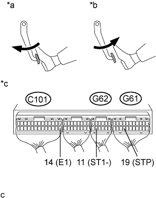
| *a | Brake pedal depressed |
| *b | Brake pedal released |
| *c | Component with harness connected (ECM) |
|
| ||||
| OK | ||
| ||
| 3.INSPECT STOP LIGHT SWITCH |
Inspect the stop light switch (See page Нажмите здесь).
|
| ||||
| OK | |
| 4.CHECK HARNESS AND CONNECTOR (ECM - STOP LIGHT SWITCH) |
Disconnect the stop light switch connector.
Disconnect the ECM connectors.
Measure the resistance according to the value(s) in the table below.
| Tester Connection | Condition | Specified Condition |
| A5-1 - G61-19 (STP) | Always | Below 1 Ω |
| A5-3 - G62-11 (ST1-) | Always | Below 1 Ω |
| Tester Connection | Condition | Specified Condition |
| A5-1 or G61-19 (STP) - Body ground | Always | 10 kΩ or higher |
| A5-3 or G62-11 (ST1-) - Body ground | Always | 10 kΩ or higher |
Reconnect the stop light switch connector.
Reconnect the ECM connector.
|
| ||||
| OK | ||
| ||
| 1.CHECK STOP LIGHT (OPERATION) |
Check if the stop lights go on and off normally when the brake pedal is depressed and released.
|
| ||||
| OK | |
| 2.CHECK ECM (STP, ST1- VOLTAGE) |
|
Turn the ignition switch to ON.
Measure the voltage according to the value(s) in the table below.
| Tester Connection | Brake Pedal Condition | Specified Condition |
| G61-19 (STP) - C101-14 (E1) | Depressed | 11 to 14 V |
| Released | Below 1.5 V | |
| G62-11 (ST1-) - C101-14 (E1) | Depressed | Below 1.5 V |
| Released | 11 to 14 V |
| *a | Brake pedal depressed |
| *b | Brake pedal released |
| *c | Component with harness connected (ECM) |
|
| ||||
| OK | ||
| ||
| 3.INSPECT STOP LIGHT SWITCH |
Inspect the stop light switch (See page Нажмите здесь).
|
| ||||
| OK | |
| 4.CHECK HARNESS AND CONNECTOR (ECM - STOP LIGHT SWITCH) |
Disconnect the stop light switch connector.
Disconnect the ECM connectors.
Measure the resistance according to the value(s) in the table below.
| Tester Connection | Condition | Specified Condition |
| A5-1 - G61-19 (STP) | Always | Below 1 Ω |
| A5-3 - G62-11 (ST1-) | Always | Below 1 Ω |
| Tester Connection | Condition | Specified Condition |
| A5-1 or G61-19 (STP) - Body ground | Always | 10 kΩ or higher |
| A5-3 or G62-11 (ST1-) - Body ground | Always | 10 kΩ or higher |
Reconnect the stop light switch connector.
Reconnect the ECM connector.
|
| ||||
| OK | ||
| ||
