СИСТЕМА ECD > Pre-heating Control Circuit |
| 1.CHECK GLOW INDICATOR LIGHT |
Turn the ignition switch to ON.
Check that the glow indicator light comes on.
|
| ||||
| OK | |
| 2.CHECK GLOW PLUG ASSEMBLY (INSTALLATION) |
Check that the glow plug assembly and glow plug wire are securely installed.
|
| ||||
| OK | |
| 3.INSPECT GLOW PLUG ASSEMBLY (RESISTANCE) |
Inspect the glow plug assembly (See page Нажмите здесь).
|
| ||||
| OK | |
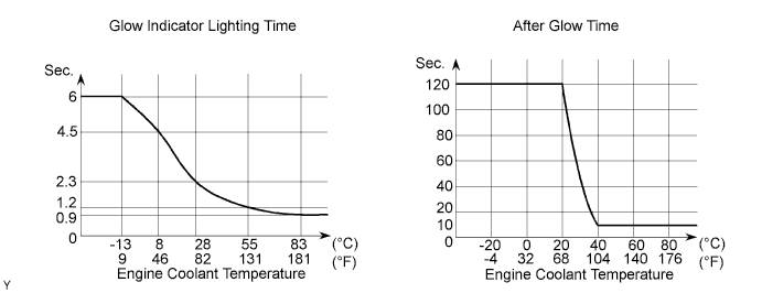
| 4.CHECK INDICATOR LIGHTING TIME AND AFTER GLOW TIME |
|
| ||||
| OK | |
| 5.READ OUTPUT DTC |
Connect the intelligent tester to the DLC3.
Turn the ignition switch to ON and turn the tester on.
Enter the following menus: Powertrain / Engine and ECT / DTC.
Read the DTCs (See page Нажмите здесь).
| Result | Proceed to |
| DTC is not output | A |
| DTC is output | B |
|
| ||||
| A | |
| 6.INSPECT GLOW RELAY ASSEMBLY |
Inspect the glow plug relay (GLOW) (See page Нажмите здесь).
|
| ||||
| OK | |
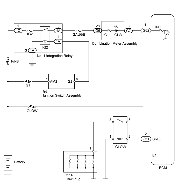
| 7.CHECK ECM (SREL VOLTAGE) |
 |
Turn the ignition switch to the start position.
Measure the voltage according to the value(s) in the table below.
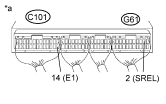
| Tester Connection | Condition | Specified Condition |
| G61-2 (SREL) - C101-14 (E1) | Cranking | 11 to 14 V |
| *a | Component with harness connected (ECM) |
|
| ||||
| OK | |
| 8.CHECK HARNESS AND CONNECTOR (GLOW RELAY - ECM AND BODY GROUND) |
Disconnect the ECM connector.
Remove the glow relay from the engine room relay block.
Measure the resistance according to the value(s) in the table below.
| Tester Connection | Condition | Specified Condition |
| G61-2 (SREL) - Relay block glow relay terminal 2 | Always | Below 1 Ω |
| Relay block glow relay terminal 1 - Body ground | Always | Below 1 Ω |
| Tester Connection | Condition | Specified Condition |
| G61-2 (SREL) or relay block glow relay terminal 2 - Body ground | Always | 10 kΩ or higher |
Reconnect the ECM connector.
Reinstall the glow relay.
|
| ||||
| OK | |
| 9.CHECK HARNESS AND CONNECTOR (GLOW PLUG RELAY (GLOW) - GLOW PLUG ASSEMBLY AND BATTERY) |
Disconnect the cable from the negative (-) battery terminal.
Disconnect the cable from the positive (+) battery terminal.
Remove the glow relay from the engine room relay block.
Disconnect the glow plug wire.
Measure the resistance according to the value(s) in the table below.
| Tester Connection | Condition | Specified Condition |
| Relay block glow relay terminal 3 - C114-1 | Always | Below 1 Ω |
| Relay block glow relay terminal 5 - Positive (+) battery terminal | Always | Below 1 Ω |
Reinstall the glow relay.
Reconnect the glow plug wire.
Reconnect the cable to the positive (+) battery terminal.
Reconnect the cable to the negative (-) battery terminal.
|
| ||||
| OK | ||
| ||
| 10.CHECK ECM (GIND VOLTAGE) |
 |
Disconnect the ECM connector.
Turn the ignition switch to ON.
Measure the voltage according to the value(s) in the table below.
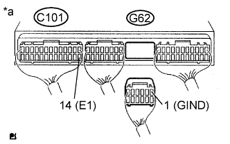
| Tester Connection | Switch Condition | Specified Condition |
| G62-1 (GIND) - C101-14 (E1) | Ignition switch ON | 11 to 14 V |
| *a | Rear view of wire harness connector (to ECM) |
Reconnect the ECM connector.
|
| ||||
| OK | ||
| ||
| 11.CHECK HARNESS AND CONNECTOR (ECM - COMBINATION METER ASSEMBLY) |
Disconnect the combination meter assembly connector.
Disconnect the ECM connector.
Measure the resistance according to the value(s) in the table below.
| Tester Connection | Condition | Specified Condition |
| G7-8 - G62-1 (GIND) | Always | Below 1 Ω |
Reconnect the combination meter assembly connector.
Reconnect the ECM connector.
|
| ||||
| OK | |
| 12.CHECK HARNESS AND CONNECTOR (COMBINATION METER ASSEMBLY - BATTERY) |
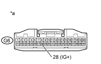 |
Disconnect the combination meter assembly connector.
Turn the ignition switch to ON.
Measure the voltage according to the value(s) in the table below.
| Tester Connection | Switch Condition | Specified Condition |
| G6-28 - Body ground | Ignition switch ON | 11 to 14 V |
| *a | Front view of wire harness connector (to Combination Meter Assembly) |
Reconnect the combination meter assembly connector.
|
| ||||
| OK | ||
| ||
