СИСТЕМА ECD > Air Conditioning Signal Circuit |
| 1.READ VALUE USING INTELLIGENT TESTER (AIR CONDITIONING SIGNAL) |
Connect the intelligent tester to the DLC3.
Start the engine.
Turn the A/C switch on.
Enter the following menus: Powertrain / Engine and ECT / Data List / A/C SIG.
| Switch Condition | A/C SIG |
| A/C switch off | OFF |
| A/C switch on | ON |
|
| ||||
| OK | ||
| ||
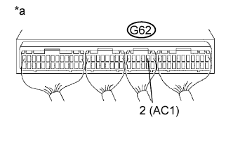
| 2.CHECK ECM (AC1 VOLTAGE) |
 |
Start the engine.
Measure the voltage according to the value(s) in the table below.
| Tester Connection | Switch Condition | Specified Condition |
| G62-2 (AC1) - Body ground | A/C switch on | Below 1.5 V |
| G62-2 (AC1) - Body ground | A/C switch off | 7.5 to 14 V |
| *a | Component with harness connected (ECM) |
|
| ||||
| OK | ||
| ||
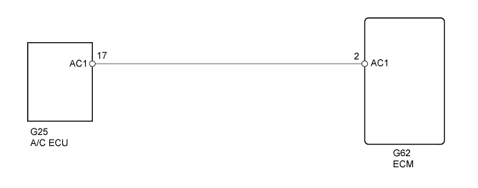
| 3.CHECK HARNESS AND CONNECTOR (ECM - AIR CONDITIONING AMPLIFIER) |
Disconnect the A/C amplifier connector.
Disconnect the ECM connector.
Measure the resistance according to the value(s) in the table below.
| Tester Connection | Condition | Specified Condition |
| G25-17 (AC1) - G62-2 (AC1) | Always | Below 1 Ω |
| Tester Connection | Condition | Specified Condition |
| G25-17 (AC1) or G62-2 (AC1) - Body ground | Always | 10 kΩ or higher |
Reconnect the A/C amplifier connector.
Reconnect the ECM connector.
|
| ||||
| OK | ||
| ||
| 1.CHECK ECM (AC1 VOLTAGE) |
|
Start the engine.
Measure the voltage according to the value(s) in the table below.
| Tester Connection | Switch Condition | Specified Condition |
| G62-2 (AC1) - Body ground | A/C switch on | Below 1.5 V |
| G62-2 (AC1) - Body ground | A/C switch off | 7.5 to 14 V |
| *a | Component with harness connected (ECM) |
|
| ||||
| OK | ||
| ||
| 2.CHECK HARNESS AND CONNECTOR (ECM - AIR CONDITIONING AMPLIFIER) |
Disconnect the A/C amplifier connector.
Disconnect the ECM connector.
Measure the resistance according to the value(s) in the table below.
| Tester Connection | Condition | Specified Condition |
| G25-17 (AC1) - G62-2 (AC1) | Always | Below 1 Ω |
| Tester Connection | Condition | Specified Condition |
| G25-17 (AC1) or G62-2 (AC1) - Body ground | Always | 10 kΩ or higher |
Reconnect the A/C amplifier connector.
Reconnect the ECM connector.
|
| ||||
| OK | ||
| ||
