DTC 19 (1) Accelerator Position Sensor Circuit Malfunction |
| DTC No. | DTC Detection Condition | Trouble Area |
| 19 (1) | Condition (a), (b), (c) or (d) continues for 2.0 seconds: (a) VPA is 0.2 V or less and VPA2 is 0.5 V or less. (b) VPA is 4.8 V or higher. (c) VPA is 0.2 V or higher and 3.45 V or less, and VPA2 is 4.8 V or higher. (d) "VPA minus VPA2" is 0.02 V or less. |
|
| Condition (a) continues for 0.5 seconds: (a) VPA is 0.2 V or less, or VPA2 is 0.5 V or less. |
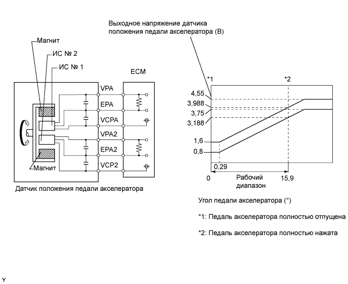
| Trouble Area | Accelerator Pedal Position Expressed as Voltage | |||
| Accelerator pedal released | Accelerator pedal depressed | |||
| ACCEL POS #1 | ACCEL POS #2 | ACCEL POS #1 | ACCEL POS #2 | |
| VC circuit open | 0 to 0.2 V | 0 to 0.2 V | 0 to 0.2 V | 0 to 0.2 V |
| VPA circuit open or shorted to ground | 0 to 0.2 V | 1.2 to 2.0 V | 0 to 0.2 V | 3.4 to 5.3 V |
| VPA2 circuit open or shorted to ground | 0.5 to 1.1 V | 0 to 0.2 V | 2.6 to 4.5 V | 0 to 0.2 V |
| E2 circuit open | 4.5 to 5.5 V | 4.5 to 5.5 V | 4.5 to 5.5 V | 4.5 to 5.5 V |
| 1.READ VALUE USING INTELLIGENT TESTER (ACCELERATOR POSITION) |
 |
Connect the intelligent tester to the DLC3.
Turn the ignition switch to ON.
Enter the following menus: Powertrain / Engine and ECT / Data List / Accel Position.
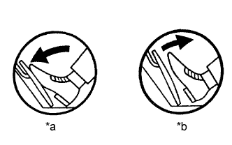
Check that the value displayed on the intelligent tester changes when repeatedly depressing and releasing the accelerator pedal.
| *a | Depressed |
| *b | Released |
|
| ||||
| OK | |
| 2.READ OUTPUT DTC (CHECK IF ACCELERATOR PEDAL POSITION SENSOR DTC IS OUTPUT AGAIN) |
Connect the intelligent tester to the DLC3.
Clear the DTC (See page Нажмите здесь).
Turn the ignition switch off for 30 seconds or more.
Start the engine and idle it for 15 seconds or more.
Read the DTCs (See page Нажмите здесь).
| Result | Proceed to |
| DTC 19 (1) output again | A |
| No DTC output | B |
|
| ||||
| A | ||
| ||
| 3.CHECK HARNESS AND CONNECTOR (ECM - ACCELERATOR PEDAL POSITION SENSOR) |
Disconnect the accelerator pedal position sensor connector.
Disconnect the ECM connector.
Measure the resistance according to the value(s) in the table below.
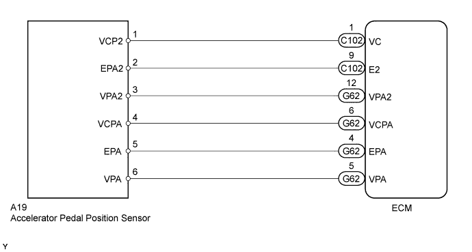
| Tester Connection | Condition | Specified Condition |
| A19-1 (VCP2) - C102-1 (VC) | Always | Below 1 Ω |
| A19-2 (EPA2) - C102-9 (E2) | Always | Below 1 Ω |
| A19-3 (VPA2) - G62-12 (VPA2) | Always | Below 1 Ω |
| A19-4 (VCPA) - G62-6 (VCPA) | Always | Below 1 Ω |
| A19-5 (EPA) - G62-4 (EPA) | Always | Below 1 Ω |
| A19-6 (VPA) - G62-5 (VPA) | Always | Below 1 Ω |
| Tester Connection | Condition | Specified Condition |
| A19-1 (VCP2) or C102-1 (VC) - Body ground | Always | 10 kΩ or higher |
| A19-2 (EPA2) or C102-9 (E2) - Body ground | Always | 10 kΩ or higher |
| A19-3 (VPA2) or G62-12 (VPA2) - Body ground | Always | 10 kΩ or higher |
| A19-4 (VCPA) or G62-6 (VCPA) - Body ground | Always | 10 kΩ or higher |
| A19-5 (EPA) or G62-4 (EPA) - Body ground | Always | 10 kΩ or higher |
| A19-6 (VPA) or G62-5 (VPA) - Body ground | Always | 10 kΩ or higher |
Reconnect the accelerator pedal position sensor connector.
Reconnect the ECM connector.
|
| ||||
| OK | |
| 4.CHECK ECM (VC, VCPA VOLTAGE) |
 |
Disconnect the accelerator pedal position sensor connector.
Turn the ignition switch to ON.
Measure the voltage according to the value(s) in the table below.
| Tester Connection | Switch Condition | Specified Condition |
| C102-1 (VC) - C102-9 (E2) | Ignition switch ON | 4.5 to 5.5 V |
| G62-6 (VCPA) - G62-4 (EPA) | Ignition switch ON | 4.5 to 5.5 V |
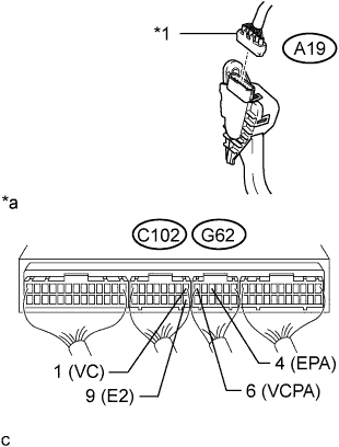
| *1 | Accelerator pedal position sensor connector |
| *a | Component with harness connected (ECM) |
Reconnect the accelerator pedal position sensor connector.
|
| ||||
| OK | |
| 5.REPLACE ACCELERATOR PEDAL ROD ASSEMBLY |
Replace the accelerator pedal rod assembly (See page Нажмите здесь).
| NEXT | |
| 6.READ OUTPUT DTC (CHECK IF ACCELERATOR PEDAL POSITION SENSOR DTC IS OUTPUT AGAIN) |
Connect the intelligent tester to the DLC3.
Clear the DTC (See page Нажмите здесь).
Turn the ignition switch off for 30 seconds or more.
Start the engine and idle it for 15 seconds or more.
Read the DTCs (See page Нажмите здесь).
| Result | Proceed to |
| DTC 19 (1) output again | A |
| No DTC output | B |
|
| ||||
| A | ||
| ||
| 1.CHECK HARNESS AND CONNECTOR (ECM - ACCELERATOR PEDAL POSITION SENSOR) |
Disconnect the accelerator pedal position sensor connector.
Disconnect the ECM connector.
Measure the resistance according to the value(s) in the table below.
| Tester Connection | Condition | Specified Condition |
| A19-1 (VCP2) - C102-1 (VC) | Always | Below 1 Ω |
| A19-2 (EPA2) - C102-9 (E2) | Always | Below 1 Ω |
| A19-3 (VPA2) - G62-12 (VPA2) | Always | Below 1 Ω |
| A19-4 (VCPA) - G62-6 (VCPA) | Always | Below 1 Ω |
| A19-5 (EPA) - G62-4 (EPA) | Always | Below 1 Ω |
| A19-6 (VPA) - G62-5 (VPA) | Always | Below 1 Ω |
| Tester Connection | Condition | Specified Condition |
| A19-1 (VCP2) or C102-1 (VC) - Body ground | Always | 10 kΩ or higher |
| A19-2 (EPA2) or C102-9 (E2) - Body ground | Always | 10 kΩ or higher |
| A19-3 (VPA2) or G62-12 (VPA2) - Body ground | Always | 10 kΩ or higher |
| A19-4 (VCPA) or G62-6 (VCPA) - Body ground | Always | 10 kΩ or higher |
| A19-5 (EPA) or G62-4 (EPA) - Body ground | Always | 10 kΩ or higher |
| A19-6 (VPA) or G62-5 (VPA) - Body ground | Always | 10 kΩ or higher |
Reconnect the accelerator pedal position sensor connector.
Reconnect the ECM connector.
|
| ||||
| OK | |
| 2.CHECK ECM (VC, VCPA VOLTAGE) |
|
Disconnect the accelerator pedal position sensor connector.
Turn the ignition switch to ON.
Measure the voltage according to the value(s) in the table below.
| Tester Connection | Switch Condition | Specified Condition |
| C102-1 (VC) - C102-9 (E2) | Ignition switch ON | 4.5 to 5.5 V |
| G62-6 (VCPA) - G62-4 (EPA) | Ignition switch ON | 4.5 to 5.5 V |
| *1 | Accelerator pedal position sensor connector |
| *a | Component with harness connected (ECM) |
Reconnect the accelerator pedal position sensor connector.
|
| ||||
| OK | |
| 3.REPLACE ACCELERATOR PEDAL ROD ASSEMBLY |
Replace the accelerator pedal rod assembly (See page Нажмите здесь).
| NEXT | |
| 4.READ OUTPUT DTC (CHECK IF ACCELERATOR PEDAL POSITION SENSOR DTC IS OUTPUT AGAIN) |
Connect the intelligent tester to the DLC3.
Clear the DTC (See page Нажмите здесь).
Turn the ignition switch off for 30 seconds or more.
Start the engine and idle it for 15 seconds or more.
Read the DTCs (See page Нажмите здесь).
| Result | Proceed to |
| DTC 19 (1) output again | A |
| No DTC output | B |
|
| ||||
| A | ||
| ||
