СИСТЕМА ECD > MIL Circuit |
| 1.CHECK MIL CONDITION |
Check the MIL condition.
| Condition | Proceed to |
| MIL remains on | A |
| MIL does not illuminate | B |
|
| ||||
| A | |
| 2.CHECK IF MIL TURNS OFF |
Connect the intelligent tester to the DLC3.
Turn the ignition switch to ON and turn the tester on.
Check if DTCs have been stored (See page Нажмите здесь). If DTCs are stored, write them down.
Clear the DTCs using the intelligent tester (See page Нажмите здесь).
Check that the MIL turns off.
|
| ||||
| OK | ||
| ||
| 3.CHECK HARNESS AND CONNECTOR (FOR SHORT) |
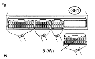 |
Disconnect the ECM connector.
Turn the ignition switch to ON.
Check that the MIL is not illuminated.
| *a | Rear view of wire harness connector (to ECM) |
Reconnect the ECM connector.
|
| ||||
| OK | ||
| ||
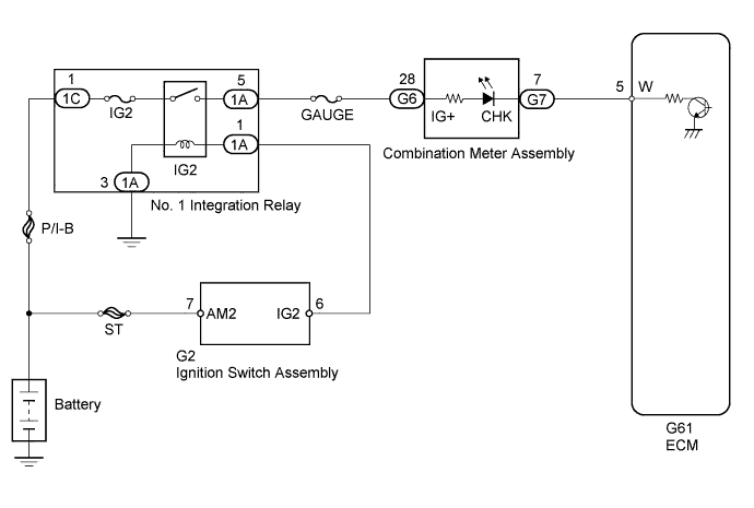
| 4.CHECK HARNESS AND CONNECTOR (ECM - COMBINATION METER ASSEMBLY) |
Disconnect the ECM connector.
Disconnect the combination meter assembly connector.
Measure the resistance according to the value(s) in the table below.
| Tester Connection | Condition | Specified Condition |
| G61-5 (W) - G7-7 (CHK) | Always | Below 1 Ω |
| Tester Connection | Condition | Specified Condition |
| G61-5 (W) or G7-7 (CHK) - Body ground | Always | 10 kΩ or higher |
Reconnect the ECM connector.
Reconnect the combination meter assembly connector.
|
| ||||
| OK | ||
| ||
| 5.CHECK IF MIL ILLUMINATES |
Check that the MIL illuminates when turning the ignition switch to ON.
|
| ||||
| OK | ||
| ||
| 6.INSPECT COMBINATION METER ASSEMBLY (MIL CIRCUIT) |
Refer to the combination meter assembly troubleshooting procedures (See page Нажмите здесь).
|
| ||||
| OK | ||
| ||
