ПРОКЛАДКА ГОЛОВКИ БЛОКА ЦИЛИНДРОВ > СНЯТИЕ |
| 1. REMOVE EXHAUST MANIFOLD |
Remove the exhaust manifold (See page Нажмите здесь).
| 2. REMOVE TIMING BELT |
Remove the timing belt (See page Нажмите здесь).
| 3. REMOVE DIESEL THROTTLE BODY |
Remove the diesel throttle body (See page Нажмите здесь).
| 4. DISCONNECT COOLER COMPRESSOR ASSEMBLY |
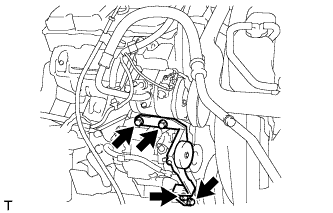 |
Remove the 4 bolts and idle pulley bracket.
 |
Disconnect the connector.
Remove the 3 bolts and disconnect the cooler compressor.
| 5. REMOVE NO. 1 COMPRESSOR MOUNTING BRACKET |
 |
Remove the bolt and disconnect the generator.
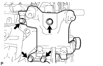 |
Remove the 4 bolts and No. 1 compressor mounting bracket.
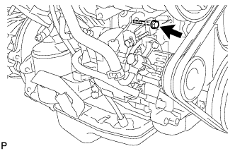
| 6. DISCONNECT HEATER WATER HOSE SUB-ASSEMBLY |
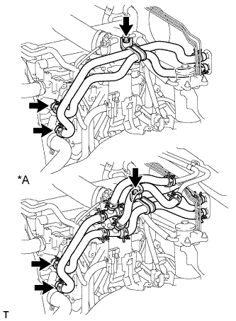 |
Remove the bolt and disconnect the heater water hoses.
| *A | for Rear Heater |
| 7. REMOVE INJECTION PIPE SET |
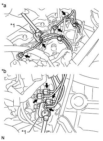 |
Using a union nut wrench, loosen the 8 union nuts of the 4 injection pipes.
| *1 | Union Nut Wrench |
| *a | for Injection Nozzle Side |
| *b | for Injection Pump Side |
Remove the 2 nuts, 2 upper pipe clamps and 4 injection pipes with 2 lower pipe clamps.
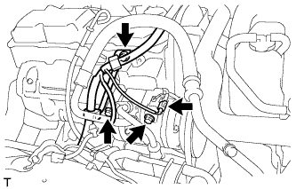
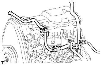
| 8. DISCONNECT WIRE HARNESS |
Remove the terminal cap.
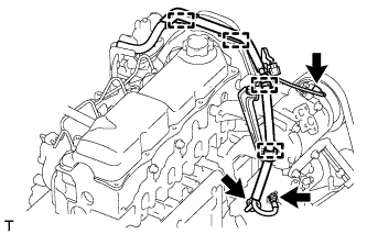 |
Remove the nut and generator wire.
Disconnect the generator connector and cooler compressor connector.
Detach the 4 wire harness clamps.
for RHD:
 |
Detach the 5 wire harness clamps.
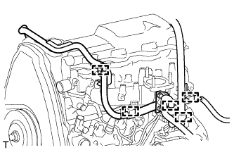
 |
for LHD:
Detach the 4 wire harness clamps.
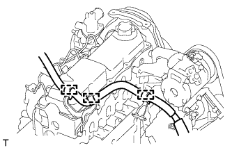 |
Detach the 3 wire harness clamps.
| 9. REMOVE WIRING HARNESS CLAMP BRACKET (for LHD) |
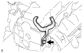 |
Remove the bolt and wiring harness clamp bracket.
| 10. REMOVE CYLINDER HEAD COVER SUB-ASSEMBLY |
Remove the 9 bolts, nut, cylinder head cover and gasket.
| 11. REMOVE CAMSHAFT |
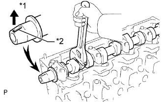 |
Turn the camshaft with a wrench so that the key groove faces upward.
| *1 | Upward |
| *2 | Key Groove |
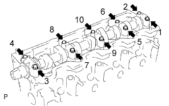 |
Uniformly loosen and remove the 10 bearing cap bolts in several steps in the sequence shown in the illustration.
Remove the 5 bearing caps and camshaft.
| 12. REMOVE CYLINDER HEAD SUB-ASSEMBLY |
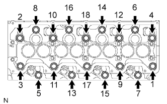 |
Uniformly loosen and remove the 18 cylinder head bolts in several steps in the sequence shown.
Lift the cylinder head from the dowels on the cylinder block to remove it, and place the cylinder head on wooden blocks on a workbench.
| 13. INSPECT CYLINDER HEAD SET BOLT |
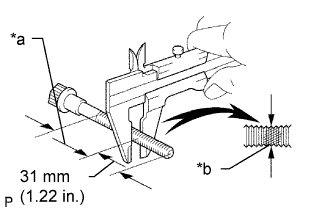 |
Using a vernier caliper, measure the minimum outer diameter of the elongated thread at the measuring point.
| *a | Measuring Point |
| *b | Elongated Thread |
| 14. REMOVE CYLINDER HEAD GASKET |
