ГЕНЕРАТОР > РАЗБОРКА |
| 1. INSPECT GENERATOR WITH VACUUM PUMP ASSEMBLY |
Mount the generator in a vise between aluminum plates.
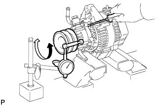 |
Insert a screwdriver to hold the generator rotor.
Install a bolt and nut to the outside of the pulley so that the bolt head and nut clamp the pulley, and then position a dial indicator as shown in the illustration.
Turn the pulley and measure the backlash between the generator rotor and vacuum pump shaft.
| 2. REMOVE VACUUM PUMP ASSEMBLY |
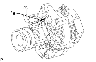 |
Place matchmarks as shown in the illustration.
| *a | Matchmark |
Remove the 4 bolts and vacuum pump.
| 3. REMOVE GENERATOR REAR END COVER |
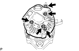 |
Remove the nut and terminal insulator.
Remove the bolt, 3 nuts, rectifier plate and rear end cover.
| 4. REMOVE GENERATOR BRUSH HOLDER ASSEMBLY |
Remove the brush holder cover.
 |
Remove the 2 screws and brush holder.
Remove the plate seal.
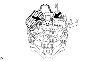
| 5. REMOVE GENERATOR REGULATOR ASSEMBLY |
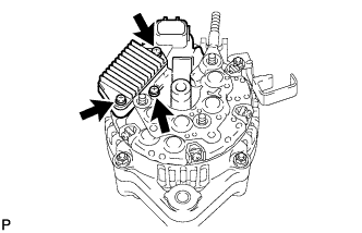 |
Remove the 3 screws and generator regulator.
| 6. REMOVE GENERATOR HOLDER WITH RECTIFIER |
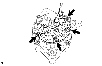 |
Remove the 4 screws and generator holder with rectifier.
Remove the 4 rubber insulators.
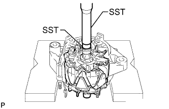
| 7. REMOVE GENERATOR RECTIFIER END FRAME |
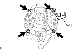 |
Remove the 4 nuts and cord clip.
| *1 | Cord Clip |
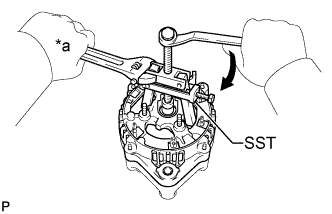 |
Using SST, remove the rectifier end frame.
| *a | Hold |
 | Turn |
Remove the washer from the rotor.
| 8. REMOVE GENERATOR ROTOR ASSEMBLY |
 |
Using SST and a press, press out the rotor.
