ТОПЛИВНАЯ СИСТЕМА ДВИГАТЕЛЯ > СХЕМА СИСТЕМЫ |
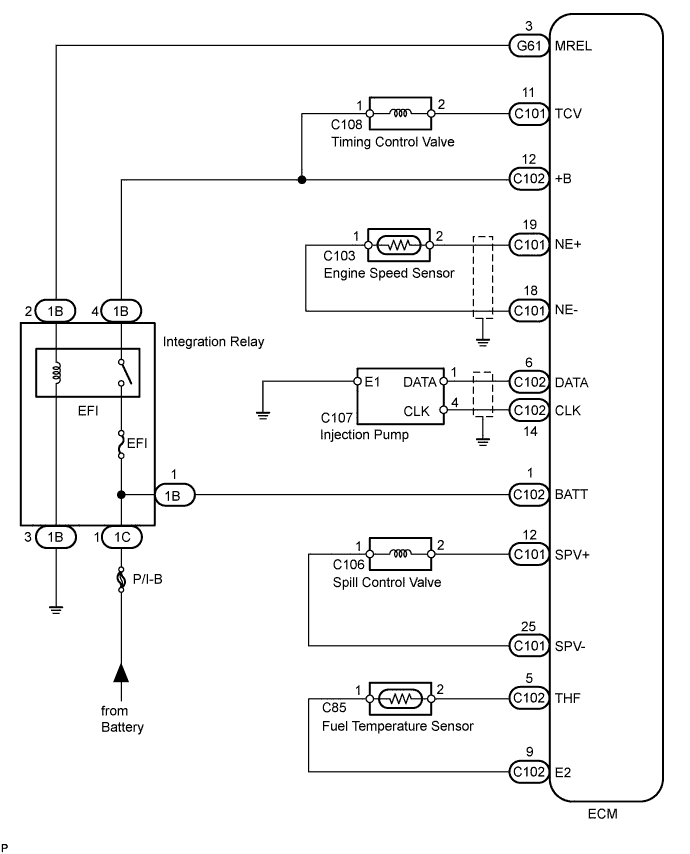
| FUEL SYSTEM DIAGRAM |
| ENGINE CONTROL SYSTEM DIAGRAM |
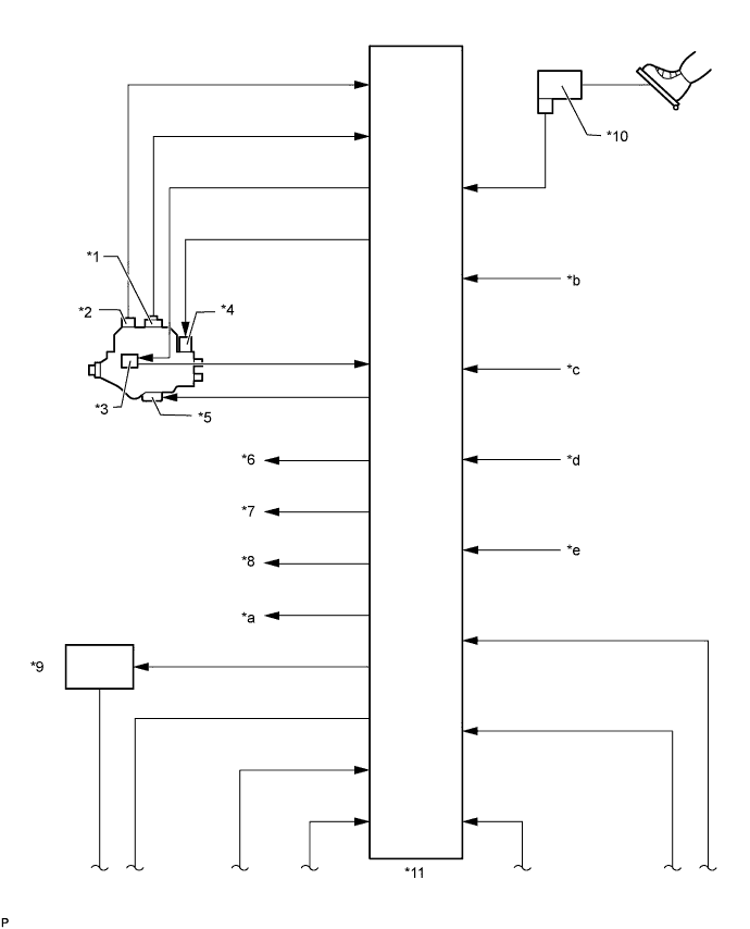
| *1 | Engine Speed Sensor | *2 | Fuel Temperature Sensor |
| *3 | Injection Pump Correction Unit | *4 | Spill Control Valve |
| *5 | Timing Control Valve | *6 | Glow Indicator Light |
| *7 | Main Relay | *8 | Tachometer |
| *9 | Glow Relay | *10 | Accelerator Pedal Position Sensor |
| *11 | ECM | - | - |
| *a | A/C Cut-off Signal | *b | Ignition Switch Signal |
| *c | Vehicle Speed Signal | *d | A/C Signal |
| *e | Starter Signal | - | - |
| ENGINE CONTROL SYSTEM DIAGRAM (CONTINUED) |
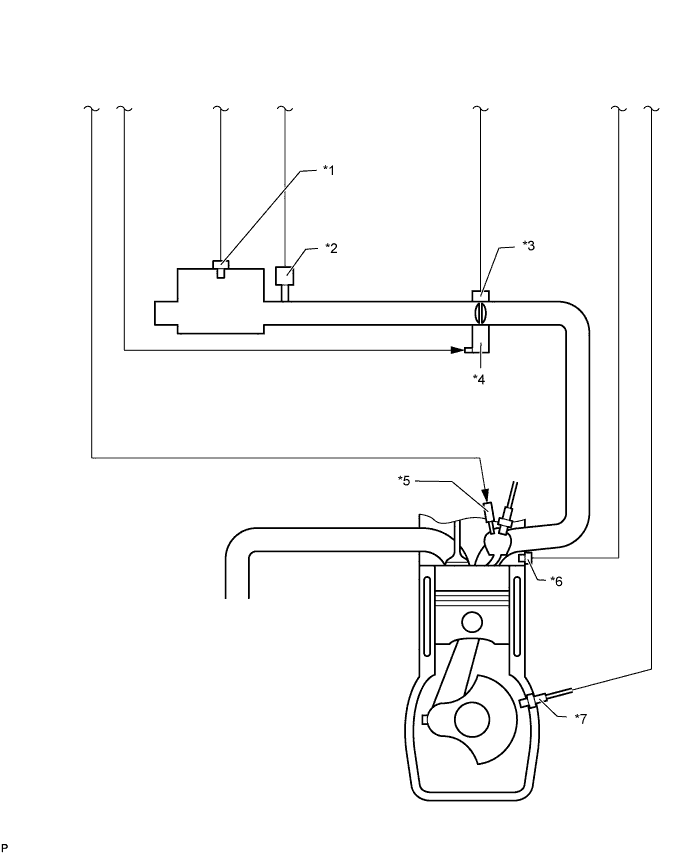
| *1 | Intake Air Temperature Sensor | *2 | Manifold Absolute Pressure Sensor |
| *3 | Throttle Open Switch | *4 | Intake Restrictor Valve Control Motor |
| *5 | Glow Plug | *6 | Engine Coolant Temperature Sensor |
| *7 | Crankshaft Position Sensor | - | - |
