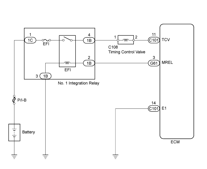
DTC 14 (4) Timing Control System Malfunction |
| DTC No. | DTC Detection Condition | Trouble Area |
| 14 (4) | During and after warming up the engine, the actual injection timing is different from the target value that the ECM calculated for several seconds. |
|
| 1.INSPECT TIMING CONTROL VALVE |
Inspect the timing control valve (See page Нажмите здесь).
|
| ||||
| OK | |
| 2.CHECK ECM (TCV VOLTAGE) |
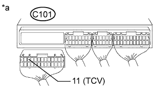 |
Disconnect the ECM connector.
Turn the ignition switch to ON.
Measure the voltage according to the value(s) in the table below.
| Tester Connection | Switch Condition | Specified Condition |
| C101-11 (TCV) - Body ground | Ignition switch ON | 11 to 14 V |
| *a | Rear view of wire harness connector (to ECM) |
Reconnect the ECM connector.
|
| ||||
| OK | |
| 3.CHECK ECM (TCV VOLTAGE, SIGNAL) |
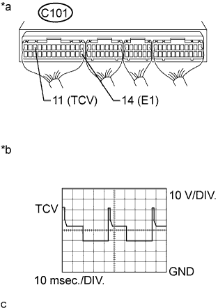 |
Turn the ignition switch to ON.
Measure the voltage according to the value(s) in the table below.
| Tester Connection | Switch Condition | Specified Condition |
| C101-11 (TCV) - C101-14 (E1) | Ignition switch ON | 11 to 14 V |
While idling, check the waveform according to the value(s) in the table below.
| Tester Connection | Condition | Specified Condition |
| C101-11 (TCV) - C101-14 (E1) | Idling | Correct waveform is as shown |
| *a | Component with harness connected (ECM) |
| *b | TCV Signal Waveform |
|
| ||||
| OK | |
| 4.CHECK LEVEL WARNING SWITCH |
Check the level warning switch (See page Нажмите здесь).
|
| ||||
| OK | |
| 5.CHECK FOR FUEL LEAK |
Visually check the injection pump, each injector and the fuel line for fuel leaks.
|
| ||||
| OK | ||
| ||
| 6.CHECK TIMING CONTROL VALVE (POWER SOURCE) |
 |
Disconnect the timing control valve connector.
Turn the ignition switch to ON.
Measure the voltage according to the value(s) in the table below.
| Tester Connection | Switch Condition | Specified Condition |
| C108-1 - Body ground | Ignition switch ON | 11 to 14 V |
| *a | Front view of wire harness connector (to Timing control valve) |
Reconnect the timing control valve connector.
|
| ||||
| OK | ||
| ||
| 7.CHECK HARNESS AND CONNECTOR (TIMING CONTROL VALVE - NO. 1 INTEGRATION RELAY (EFI)) |
Disconnect the timing control valve connector.
Disconnect the No. 1 integration relay (EFI) connector from the engine room junction block.
Measure the resistance according to the value(s) in the table below.
| Tester Connection | Condition | Specified Condition |
| C108-1 - 1B-4 | Always | Below 1 Ω |
| Tester Connection | Condition | Specified Condition |
| C108-1 or 1B-4 - Body ground | Always | 10 kΩ or higher |
Reconnect the timing control valve connector.
Reconnect the No. 1 integration relay (EFI) connector.
|
| ||||
| OK | ||
| ||
