DTC 18 (5) Spill Control Circuit Malfunction |
| DTC No. | DTC Detection Condition | Trouble Area |
| 18 (5) | Open or short in the spill control valve circuit at 500 rpm or more. |
|
| 1.INSPECT SPILL CONTROL VALVE |
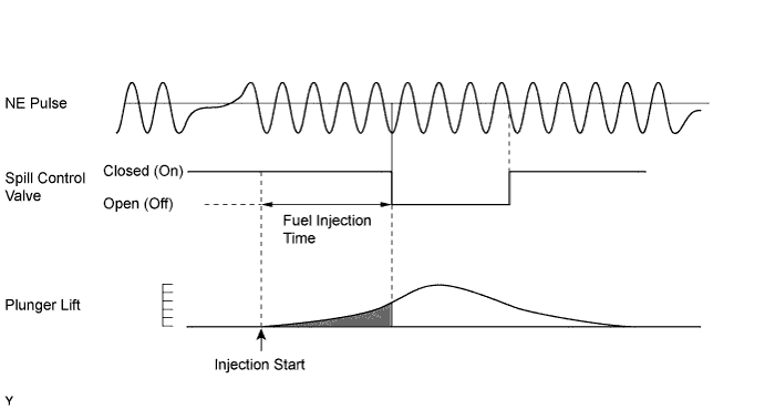
Inspect the spill control valve (See page Нажмите здесь).
|
| ||||
| OK | |
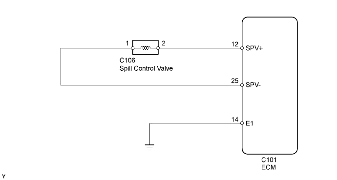
| 2.CHECK ECM (SPV+ VOLTAGE) |
 |
Disconnect the spill control valve connector.
Turn the ignition switch to ON.
Measure the voltage according to the value(s) in the table below.
| Tester Connection | Switch Condition | Specified Condition |
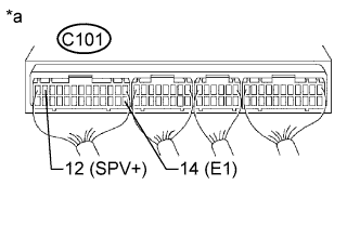
| C101-12 (SPV+) - C101-14 (E1) | Ignition switch ON | 11 to 14 V |
| *a | Component with harness connected (ECM) |
Reconnect the spill control valve connector.
|
| ||||
| OK | |
| 3.CHECK ECM (SPV- VOLTAGE) |
 |
Turn the ignition switch to ON.
Measure the voltage according to the value(s) in the table below.
| Tester Connection | Switch Condition | Specified Condition |
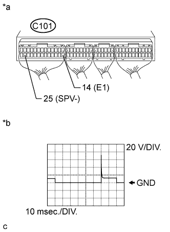
| C101-25 (SPV-) - C101-14 (E1) | Ignition switch ON | 11 to 14 V |
While idling, check the waveform with an oscilloscope connected between the specified terminals of the ECM connector.
| Tester Connection | Condition | Specified Condition |
| C101-25 (SPV-) - C101-14 (E1) | Idling | Correct waveform is as shown |
| *a | Component with harness connected (ECM) |
| *b | SPV- signal waveform |
|
| ||||
| OK | ||
| ||
| 4.CHECK HARNESS AND CONNECTOR (ECM - SPILL CONTROL VALVE) |
Disconnect the spill control valve connector.
Disconnect the ECM connector.
Measure the resistance according to the value(s) in the table below.
| Tester Connection | Condition | Specified Condition |
| C106-2 - C101-12 (SPV+) | Always | Below 1 Ω |
| C106-1 - C101-25 (SPV-) | Always | Below 1 Ω |
| Tester Connection | Condition | Specified Condition |
| C106-2 or C101-12 (SPV+) - Body ground | Always | 10 kΩ or higher |
| C106-1 or C101-25 (SPV-) - Body ground | Always | 10 kΩ or higher |
Reconnect the spill control valve connector.
Reconnect the ECM connector.
|
| ||||
| OK | ||
| ||
