PARK ASSIST / MONITORING TOYOTA PARKING ASSIST-SENSOR SYSTEM CONTROL TOYOTA PARKING ASSIST-SENSOR CONTROL
FUNCTION OF MAIN COMPONENTS
| Component | Function |
|---|---|
|
*1: Models with advanced park *2: Models with headup display *3: Models with multi-display assembly *4: Models with radio and display receiver assembly *5: Models with panoramic view monitor system *6: Models with parking assist monitor system |
|
| Front Corner Ultrasonic Sensor RH/LH | Sends ultrasonic waves to detect stationary objects and outputs a signal to the clearance warning ECU assembly. |
| Front Center Ultrasonic Sensor RH/LH | |
| Front Side Ultrasonic Sensor RH/LH*1 | |
| Rear Center Ultrasonic Sensor RH/LH | |
| Rear Center Ultrasonic Sensor RH/LH | |
| Rear Side Ultrasonic Sensor RH/LH*1 | |
| Side Television Camera Assembly RH/LH | Detects stationary objects, moving objects and sends a signal to the parking assist ECU.*1 |
| Clearance Warning ECU Assembly | ·
Determines system operation conditions based on signals input from each switch. ·
Amplifies/processes waves received from the ultrasonic sensors, determines stationary objects, controls operation of the indicator lights, No. 1 clearance warning buzzer, and No. 2 clearance warning buzzer, and determines sensor abnormalities. ·
Controls operation of the No. 1 clearance warning buzzer and No. 2 clearance warning buzzer, and sends a display request signal, etc. to the headup display*2, multi-display assembly*3 or radio and display receiver assembly*4 and combination meter assembly, based on stationary object detection data and abnormality judgment. |
| Combination Meter Assembly
·
Toyota Parking Assist-sensor System OFF Indicator ·
Multi-information Display |
·
Sends a Toyota parking assist-sensor system on/off signal to the clearance warning ECU assembly. ·
Receives stationary object detection signals from the clearance warning ECU assembly, and displays Toyota parking assist-sensor system detection on the multi-information display. ·
When the Toyota parking assist-sensor system is off, turns the Toyota parking assist-sensor system OFF indicator on. ·
Sends a customization signal to the clearance warning ECU assembly. ·
When a malfunction is detected in the Toyota parking assist-sensor system or the ultrasonic sensors determine that control is not possible, the Toyota parking assist-sensor system OFF indicator illuminates and a message is displayed on the multi-information display to warn the driver. |
| No. 1 Clearance Warning Buzzer | Changes the buzzer sound by controlling the clearance warning ECU assembly, in order to notify the driver of the approximate distance from the vehicle to a stationary object toward the front. |
| No. 2 Clearance Warning Buzzer | Changes the buzzer sound by controlling the clearance warning ECU assembly, in order to notify the driver of the approximate distance from the vehicle to a stationary object toward the rear. |
| Headup Display (Meter Mirror Sub-assembly)*2 | Receives stationary object detection signals from the clearance warning ECU assembly, and performs Toyota parking assist-sensor detection display. |
| Multi-display Assembly*3 | Displays Toyota parking assist-sensor system detection when a stationary object is detected. |
| Radio and Display Receiver Assembly*4 | |
| EV Control ECU | Sends a shift position signal to the clearance warning ECU assembly. |
| Parking Assist ECU*5 | Sends a stationary object detection video signal to the multi-display assembly *3 or radio and display receiver assembly*4, based on stationary object detection signals received from the clearance warning ECU assembly. |
| Rear Television Camera Assembly*6 | |
| Brake Actuator Assembly
·
No. 2 Skid Control ECU |
Sends a vehicle speed signal to the clearance warning ECU assembly. |
| Air Conditioning Amplifier Assembly | Sends an outside temperature signal to the clearance warning ECU assembly. |
| Central Gateway ECU (Network Gateway ECU) | Relays the signal between the CAN communication buses. |
| DLC3 | ·
The Global TechStream (GTS) can be connected to read the Diagnostic Trouble Codes (DTCs) of malfunctions. ·
The Global TechStream (GTS) can be connected to change settings as desired by the user. |
OPERATING CONDITION
When all of the conditions in the table below are established, the system performs stationary object detection.
Power source mode is turned on (IG).
Toyota parking assist-sensor system is on.
The shift position is not P.
The vehicle speed is approximately 10 km/h (6 mph) or less.
When all of the conditions in the table below are established, the object warning function will operate. (Models with Advanced Park)
The shift position is not R.
After the D shift position has been selected, the vehicle has moved 7 m(23.0 ft.) or less*.
Camera switch has been pressed and the panoramic view monitor screen is displayed.
The advanced park is operating.
An object is detected by a side sensor or side camera.
- HINT:
-
*: If the shift position was changed from N to D, the function will not operate.
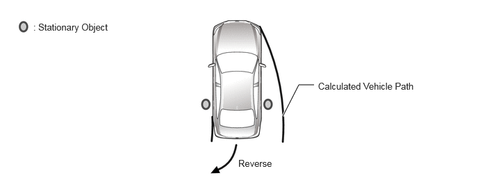
As for stationary objects in side areas, a warning will be displayed on the multi-information display, multi-display and headup display* and a warning buzzer will sound only if the objects are within the vehicle path. (Models with Object Warning Function)
*: Models with headup display
SYSTEM CONTROL
Toyota Parking Assist-sensor System Detection Area
Stationary objects are detected within approximately 600 mm (23.6 in.) of the front left and right corner sensors, within approximately 1000 mm (39.4 in.) of the front left and right center sensors, and within approximately 1500 mm (59.1 in.) of the rear left and right center sensors. Note that there are some areas where stationary objects cannot be detected if they are too close to the bumper. The detection range may also vary depending on the shape of the stationary object.
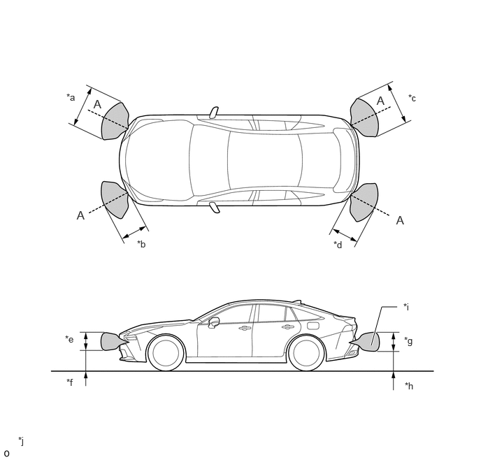
| *a | Approximately 900 mm (35.4 in.) | *b | Approximately 600 mm (23.6 in.) |
| *c | Approximately 940 mm (37.0 in.) | *d | Approximately 600 mm (23.6 in.) |
| *e | Approximately 300 mm (11.8 in.) | *f | Approximately 450 mm (17.7 in.) |
| *g | Approximately 320 mm (12.6 in.) | *h | Approximately 370 mm (14.6 in.) |
| *i | Sensor Front (Cross Section A)Detection Area (Not Detection Areatoward Front/Rear of Vehicle) | *j | The detection area in the illustration was calculated using a pole with adiameter of 60 mm (2.36 in.). |

|
Detection Area | - | - |
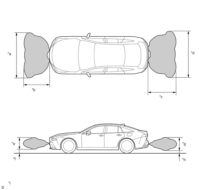
| *a | Approximately 1900 mm (74.8 in.) | *b | Approximately 1000 mm (39.4 in.) |
| *c | Approximately 2000 mm (78.7 in.) | *d | Approximately 1500 mm (59.1 in.) |
| *e | Approximately 570 mm (22.4 in.) | *f | Approximately 240 mm (9.45 in.) |
| *g | Approximately 700 mm (27.6 in.) | *h | Approximately 180 mm (7.09 in.) |
| *i | The detection area in the illustration was calculated using a pole with a diameter of 60 mm (2.36 in.). | - | - |
|
|
Detection Area | - | - |
Warning Buzzer Sounding
The warning buzzer sound changes according to the distance from an identified stationary object.
The buzzer sounding interval changes approximately every 100 mm (3.94 in.)*1 or 150 mm (5.91 in.) - 100 mm (3.94 in.)*2 according to the distance from the stationary object.
*1: Models without advanced park
*2: Models with advanced park
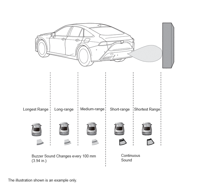
| Identification Level | Detection Distance [mm (in.)] | Buzzer Sound |
|---|---|---|
|
*1: Front center sensor detection only *2: Rear center sensor detection only |
||
| Longest Range | 1000 (39.4) - 600 (23.6)*1
1500 (59.1) - 600 (23.6)*2 |
The sound interval changes every 100 mm (3.94 in.), and then sounds intermittently. |
| Long-range | 600 (23.6) - 450 (17.7) | |
| Medium-range | 450 (17.7) - 300 (11.8) | |
| Short-range | 300 (11.8) - 150 (5.91) | Sounds consecutively. |
| Shortest Range | 150 (5.91) or less | |
| Identification Level | Detection Distance [mm (in.)] | Buzzer Sound |
|---|---|---|
| Longest Range | 1250 (49.2) - 600 (23.6) | ·
At the detection distance from 1250 mm (49.2 in.) to 900 mm (3.54 in.), the sound interval changes every 150 mm (5.91 in.) , and then sounds intermittently. ·
At the detection distance from 900 mm (3.54 in.) to 300 mm (11.8 in.), the sound interval changes every 100 mm (3.94 in.), and then sounds intermittently. |
| Long-range | 600 (23.6) - 450 (17.7) | |
| Medium-range | 450 (17.7) - 300 (11.8) | |
| Short-range | 300 (11.8) - 150 (5.91) | Sounds consecutively. |
| Shortest Range | 150 (5.91) or less |
If sensors detect multiple stationary objects, the buzzer sounds according to the distance from the closest stationary object.
- HINT:
-
*: The Toyota parking assist-sensor warning buzzer does not sound if the RCTA or RCD (models with rear camera detection) warning buzzer is sounding.
FUNCTION
Toyota Parking Assist-sensor System Operation
The combination meter assembly customization setting can be used to turn the Toyota parking assist-sensor system on and off.
A Toyota parking assist-sensor system off indicator is located in the combination meter assembly to make it possible to check that the Toyota parking assist-sensor system is off.
Warning Buzzer Mute Function
When the warning buzzer is sounding, it is automatically muted if any of the following conditions are established.
There is no change to the distance from the stationary object over a certain period of time.
The distance between the vehicle and stationary object increases.
The stationary object is removed from the path.
When the warning buzzer has been automatically muted, it once again begins sounding if any of the following conditions are established.
A stationary object is detected within short-range.
The vehicle approaches a stationary object.
A stationary object that was out of the path of the vehicle is now on the path of the vehicle.
When the warning buzzer is sounding, the warning buzzer is temporarily muted if the steering pad switch assembly is used to do so.
When the warning buzzer has been temporarily muted, temporary muting is canceled if any of the following conditions are established.
The shift status is changed.
The vehicle speed reaches a certain value or higher.
There is a sensor abnormality (open/frozen).
It cannot be used (CAN communication abnormality).
The Toyota parking assist-sensor system was turned off.
The power source mode is turned off.
Abnormality Judgment
When the Toyota parking assist-sensor system is turned on, abnormality judgment is performed on all sensors regardless of the shift position.
If there is an open or frozen sensor, or if there is a communication malfunction in the clearance warning ECU, a Toyota parking assist-sensor off indicator illuminates and a warning is displayed on the multi-information display.
When "Clean Parking Assist Sensor" (a malfunction condition) is displayed, the location of the dirty sensor is displayed on the multi-information display.
Toyota Parking Assist-sensor System Settings
The combination meter assembly customization setting can be used to change the volume of the buzzer (3 levels).
The Global TechStream (GTS) can be connected to change settings for some functions as desired by the user. Refer to the Repair Manual for details.
DIAGNOSIS
In order to make system inspections easier to perform, a diagnosis function is used in consideration of serviceability. The DTCs of malfunctioning parts can be read by connecting the Global TechStream (GTS). Refer to the Repair Manual for details.