NM37H0E
_58
Vehicle Interior
_097853
HEATING / AIR CONDITIONING
_0466362
AIR CONDITIONING SYSTEM
DE
DETAILS
F
HEATING / AIR CONDITIONING AIR CONDITIONING SYSTEM DETAILS AIR CONDITIONING CONTROL PANEL
CONSTRUCTION
a.
Operation switches are placed on the multi-display assembly* and air conditioning control assembly that are positioned at the center of the instrument panel.
- HINT:
-
*: Models with multi-display assembly
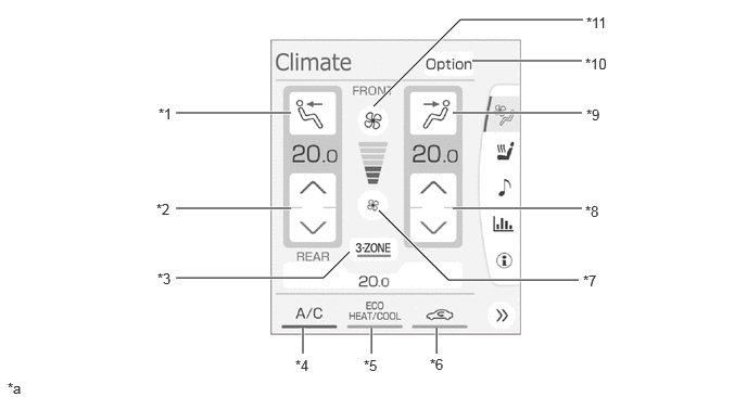
Top Screen (FRONT) (Models with Multi-zone (3-ZONE) Climate Control
4.531,0.583 5.583,0.583
true
4.344,1.083 5.583,1.083
true
3.583,1.021 4.417,0.188
4.417,0.188 5.594,0.188
true
4.344,2 5.583,2
true
3.635,2.021 4.302,2.688
4.302,2.688 5.552,2.688
true
1.688,1.083 2.792,1.083
true
1.688,2 2.792,2
true
1.688,2.667 3.104,2.667
3.104,2.667 3.354,2.417
true
2.906,3.146 2.906,3.396
true
3.563,3.146 3.563,3.396
true
4.188,3.146 4.188,3.396
true
1.521,1.01 1.823,1.167
0.302,0.156
10
false
*1
1.5,1.927 1.771,2.083
0.271,0.156
10
false
*2
1.51,2.594 1.802,2.75
0.292,0.156
10
false
*3
2.833,3.427 3.115,3.583
0.281,0.156
10
false
*4
3.49,3.427 3.781,3.573
0.292,0.146
10
false
*5
4.125,3.417 4.375,3.677
0.25,0.26
10
false
*6
5.594,2.615 5.896,2.823
0.302,0.208
10
false
*7
5.615,1.948 6,2.156
0.385,0.208
10
false
*8
5.625,1.021 6.021,1.229
0.396,0.208
10
false
*9
5.615,0.531 6.104,0.688
0.49,0.156
10
false
*10
5.625,0.135 6.104,0.281
0.479,0.146
10
false
*11
0.073,3.646 0.385,3.802
0.313,0.156
10
false
*a
| *1 | Left Side Mode Setting Switch | *2 | Left Side Temperature Setting Switch |
| *3 | 3-ZONE Switch | *4 | A/C Switch |
| *5 | ECO and HEAT and COOL Switch | *6 | Fresh/Recirculation Switch |
| *7 | Blower Switch (Blower Down) | *8 | Right Side Temperature Setting Switch |
| *9 | Right Side Mode Setting Switch | *10 | Option Switch |
| *11 | Blower Switch (Blower Up) | - | - |
| *a | The illustration shown are example only. The settings of each switch and display differ depending on the specifications. | - | - |
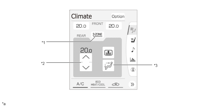
Top Screen (REAR) (Models with Multi-zone (3-ZONE) Climate Control
1.667,1.5 3.25,1.5
3.25,1.5 3.417,1.333
true
1.667,2.25 2.917,2.25
true
4.083,2.333 5.479,2.333
true
1.5,1.448 7.156,2
5.656,0.552
10
false
*1
1.479,2.198 1.844,2.583
0.365,0.385
10
false
*2
5.542,2.271 7.156,2.75
1.615,0.479
10
false
*3
0.073,3.646 0.385,3.802
0.313,0.156
10
false
*a
| *1 | 3-ZONE Switch | *2 | Rear Passenger Temperature Setting Switch |
| *3 | Rear Passenger Mode Setting Switch | - | - |
| *a | The illustration shown are example only. The settings of each switch and display differ depending on the specifications. | - | - |
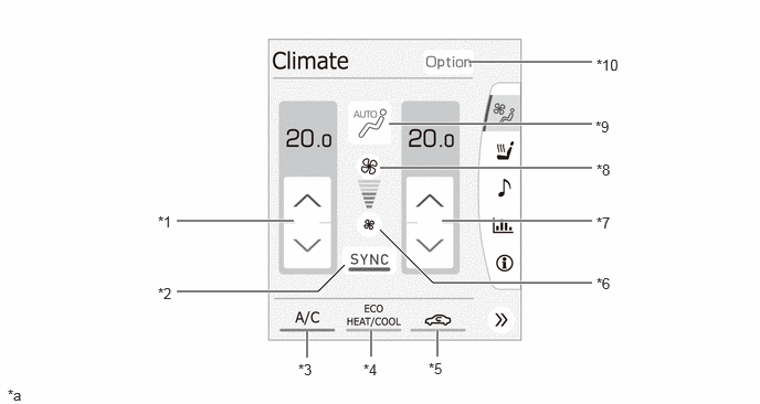
Top Screen (Models with Left and Right Independent Temperature Control)
4.417,0.583 5.583,0.583
true
4.167,2.083 5.583,2.083
true
3.583,2.167 4.083,2.667
4.083,2.667 5.583,2.667
true
1.667,2.083 2.771,2.083
true
1.667,2.75 3,2.75
3,2.75 3.25,2.5
true
2.896,3.125 2.896,3.375
true
3.5,3.115 3.5,3.365
true
4.125,3.115 4.125,3.365
true
3.583,1.583 5.583,1.583
true
3.667,1.167 5.583,1.167
true
1.49,2.01 1.75,2.167
0.26,0.156
10
false
*1
1.49,2.688 1.781,2.844
0.292,0.156
10
false
*2
2.813,3.406 3.094,3.563
0.281,0.156
10
false
*3
3.427,3.406 3.719,3.552
0.292,0.146
10
false
*4
4.042,3.396 4.292,3.656
0.25,0.26
10
false
*5
5.625,2.594 5.938,2.802
0.313,0.208
10
false
*6
5.625,2.021 6.01,2.24
0.385,0.219
10
false
*7
5.625,1.521 6.021,1.729
0.396,0.208
10
false
*8
5.615,1.115 6.354,1.5
0.74,0.385
10
false
*9
5.625,0.531 6.427,1
0.802,0.469
10
false
*10
0.073,3.646 0.385,3.802
0.313,0.156
10
false
*a
| *1 | Left Side Temperature Setting Switch | *2 | SYNC Switch |
| *3 | A/C Switch | *4 | ECO and HEAT and COOL Switch |
| *5 | Fresh/Recirculation Switch | *6 | Blower Switch (Blower Down) |
| *7 | Right Side Temperature Setting Switch | *8 | Blower Switch (Blower Up) |
| *9 | Mode Setting Switch | *10 | Option Switch |
| *a | The illustration shown are example only. The settings of each switch and display differ depending on the specifications. | - | - |
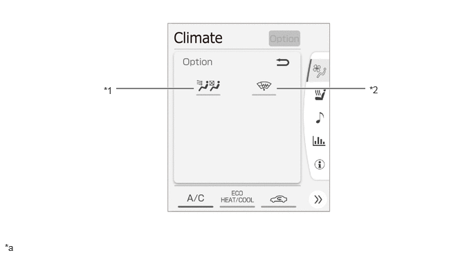
Option Screen
1.75,1.333 2.917,1.333
true
4.167,1.333 5.5,1.333
true
1.563,1.281 1.917,1.51
0.354,0.229
10
false
*1
5.563,1.271 6.083,1.458
0.521,0.188
10
false
*2
0.073,3.646 0.385,3.802
0.313,0.156
10
false
*a
| *1 | S-FLOW Switch | *2 | Windshield Deicer Switch |
| *a | The illustration shown are example only. The settings of each switch and display differ depending on the specifications. | - | - |
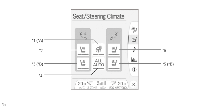
Seat/Steering Climate
1.583,2.667 3.25,2.667
3.25,2.667 3.5,2.417
true
1.583,1.417 3.333,1.417
3.333,1.417 3.5,1.583
true
1.583,1.781 2.75,1.781
true
1.583,2.26 2.75,2.26
true
4.25,1.771 5.75,1.771
true
4.25,2.26 5.75,2.26
true
1.385,2.615 7.156,2.896
5.771,0.281
10
false
*4
0.073,3.646 0.385,3.802
0.313,0.156
10
false
*a
1.135,2.198 7.156,2.406
6.021,0.208
10
false
*3 (*B)
1.396,1.719 7.156,1.948
5.76,0.229
10
false
*2
1.135,1.354 7.156,1.604
6.021,0.25
10
false
*1 (*A)
5.792,1.708 7.156,2.271
1.365,0.563
10
false
*6
5.792,2.198 7.156,2.781
1.365,0.583
10
false
*5 (*B)
| *A | Models with Steering Wheel Heater System | *B | Models with Climate Control Seat System |
| *1 | Steering Wheel Heater Switch | *2 | Front Seat Heater Switch LH |
| *3 | Front Seat Ventilation Switch LH | *4 | ALL AUTO Switch |
| *5 | Front Seat Ventilation Switch RH | *6 | Front Seat Heater Switch RH |
| *a | The illustration shown are example only. The settings of each switch and display differ depending on the specifications. | - | - |
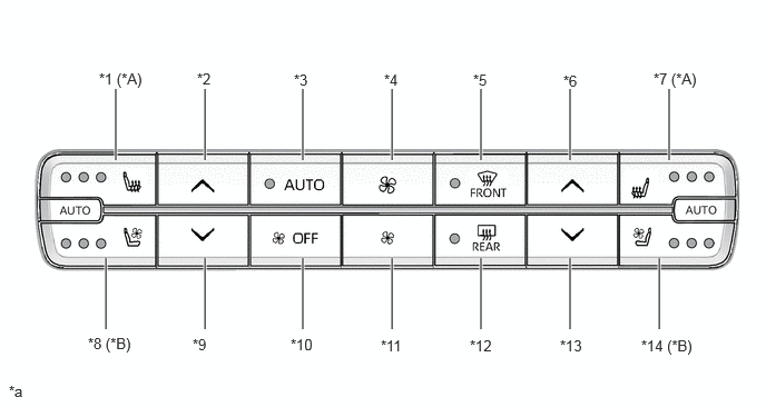
Air Conditioning Control Assembly (Models with Multi-display Assembly)
1.083,0.833 1.083,1.5
true
1.917,0.833 1.917,1.5
true
2.833,0.833 2.833,1.5
true
3.667,0.833 3.667,1.5
true
4.5,0.833 4.5,1.5
true
5.333,0.833 5.333,1.5
true
6.26,0.833 6.26,1.5
true
1.917,2.417 1.917,3.083
true
2.833,2.417 2.833,3.083
true
3.667,2.417 3.667,3.083
true
4.5,2.417 4.5,3.083
true
5.333,2.417 5.333,3.083
true
6.167,2.417 6.167,3.083
true
0.99,2.417 0.99,3.083
true
0.927,0.656 1.49,0.875
0.563,0.219
10
false
*1 (*A)
0.083,3.583 0.396,3.781
0.313,0.198
10
false
*a
1.844,0.656 2.156,0.854
0.313,0.198
10
false
*2
2.75,0.667 3.042,0.875
0.292,0.208
10
false
*3
3.594,0.667 4.052,1.031
0.458,0.365
10
false
*4
4.427,0.667 4.854,1.177
0.427,0.51
10
false
*5
5.271,0.677 5.573,0.958
0.302,0.281
10
false
*6
6.115,0.656 6.677,0.865
0.563,0.208
10
false
*7 (*A)
0.823,3.135 1.5,3.458
0.677,0.323
10
false
*8 (*B)
1.802,3.146 2.229,3.469
0.427,0.323
10
false
*9
2.719,3.146 3.354,3.458
0.635,0.313
10
false
*10
3.563,3.156 3.917,3.448
0.354,0.292
10
false
*11
6,3.156 6.75,3.573
0.75,0.417
10
false
*14 (*B)
4.396,3.156 4.76,3.448
0.365,0.292
10
false
*12
5.24,3.156 5.573,3.385
0.333,0.229
10
false
*13
| *A | Models with Climate Control Seat System | *B | Models with Seat Heater System, Climate Control Seat System |
| *C | Models with Seat Heater System | - | - |
| *1 | Front Seat Heater Switch LH | *2 | Left Side Temperature Setting Switch (Up) |
| *3 | AUTO Switch | *4 | Blower Switch (Blower Up) |
| *5 | Windshield Defroster Switch | *6 | Right Side Temperature Setting Switch (Up) |
| *7 | Front Seat Heater Switch RH | *8 | Front Seat Ventilation Switch LH |
| *9 | Left Side Temperature Setting Switch (Down) | *10 | OFF Switch |
| *11 | Blower Switch (Blower Down) | *12 | Rear Window Defogger and Mirror Heater Switch |
| *13 | Right Side Temperature Setting Switch (Down) | *14 | Front Seat Ventilation Switch RH |
| *a | The illustration shown are example only. The settings of each switch and display differ depending on the specifications. | - | - |
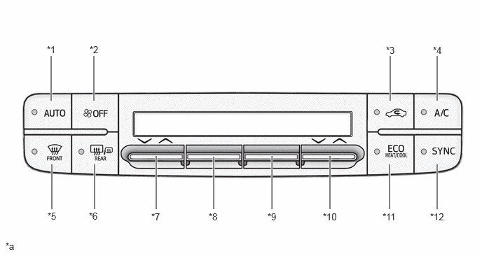
Air Conditioning Control Assembly (Models without Multi-display Assembly)
0.76,0.833 0.76,1.5
true
1.396,0.833 1.396,1.5
true
5.802,0.833 5.802,1.5
true
6.5,0.833 6.5,1.5
true
1.406,2.448 1.406,3.115
true
2.323,2.323 2.323,3.115
true
3.177,2.333 3.177,3.115
true
4.042,2.323 4.042,3.115
true
5.792,2.448 5.792,3.115
true
6.5,2.448 6.5,3.115
true
0.771,2.448 0.771,3.115
true
4.906,2.323 4.906,3.115
true
0.698,0.656 1.49,0.906
0.792,0.25
10
false
*1
0.708,3.135 1.104,3.469
0.396,0.333
10
false
*5
0.083,3.583 0.396,3.781
0.313,0.198
10
false
*a
1.333,0.656 2.156,0.927
0.823,0.271
10
false
*2
5.74,0.667 7.021,1.281
1.281,0.615
10
false
*3
6.438,0.667 6.948,1.115
0.51,0.448
10
false
*4
1.323,3.135 1.719,3.448
0.396,0.313
10
false
*6
2.25,3.146 2.708,3.448
0.458,0.302
10
false
*7
3.104,3.146 3.354,3.406
0.25,0.26
10
false
*8
3.979,3.146 4.26,3.438
0.281,0.292
10
false
*9
6.396,3.146 6.75,3.542
0.354,0.396
10
false
*12
4.802,3.146 5.104,3.438
0.302,0.292
10
false
*10
5.688,3.146 6.281,3.479
0.594,0.333
10
false
*11
| *1 | AUTO Switch | *2 | OFF Switch |
| *3 | Fresh/Recirculation Switch | *4 | A/C Switch |
| *5 | Windshield Defroster Switch | *6 | Rear Window Defogger and Mirror Heater Switch |
| *7 | Left Side Temperature Setting Switch | *8 | Blower Switch |
| *9 | Mode Setting Switch | *10 | Right Side Temperature Setting Switch |
| *11 | ECO and HEAT and COOL Switch | *12 | SYNC Switch |
| *a | The illustration shown are example only. The settings of each switch and display differ depending on the specifications. | - | - |
b.
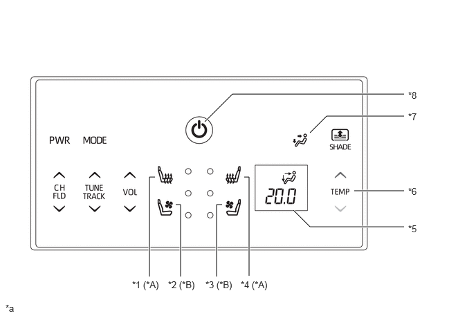
A cooler control switch assembly that can be used to operate the rear cooler from the rear seats is provided depending on the model. The installation position of the cooler control switch assembly is the center armrest of the rear seats.
Cooler Control Switch Assembly
4.667,2 4.917,1.75
4.917,1.75 6.083,1.75
true
6.083,2.875 5.333,2.875
true
3.083,1.833 3.5,1.417
3.5,1.417 6.083,1.417
true
3.75,4.156 3.75,2.667
3.75,2.667 3.677,2.667
true
3.26,4.167 3.26,3.083
3.26,3.083 3.344,3.083
true
2.719,4.167 2.719,3.083
2.719,3.083 2.646,3.083
true
2.25,4.167 2.25,2.667
2.25,2.667 2.333,2.667
true
4.417,3.167 4.667,3.417
4.667,3.417 6.083,3.417
true
6.146,1.354 7.156,1.542
1.01,0.188
10
false
*8
3.625,4.208 7.156,4.813
3.531,0.604
10
false
*4 (*A)
0.083,4.563 0.396,4.719
0.313,0.156
10
false
*a
6.146,1.677 7.156,1.865
1.01,0.188
10
false
*7
6.146,2.802 7.156,2.99
1.01,0.188
10
false
*6
3.094,4.208 7.135,4.813
4.042,0.604
10
false
*3 (*B)
2.531,4.208 3.188,4.438
0.656,0.229
10
false
*2 (*B)
1.99,4.208 7.135,4.708
5.146,0.5
10
false
*1 (*A)
6.146,3.365 7.156,3.99
1.01,0.625
10
false
*5
| *A | Models with Seat Heater System | *B | Models with Climate Control Seat System |
| *1 | Rear Seat Heater Switch LH | *2 | Rear Seat Ventilation Switch LH |
| *3 | Rear Seat Ventilation Switch RH | *4 | Rear Seat Heater Switch RH |
| *5 | Display | *6 | Temperature Setting Switch |
| *7 | Mode Setting Switch | *8 | Power ON/OFF Switch |
| *a | The illustration shown are example only. The settings of each switch and display differ depending on the specifications. | - | - |