NM37H0E
_58
Vehicle Interior
_097853
HEATING / AIR CONDITIONING
_0466362
AIR CONDITIONING SYSTEM
DE
DETAILS
F
HEATING / AIR CONDITIONING AIR CONDITIONING SYSTEM DETAILS THREE WAY VALVE
CONSTRUCTION
a.
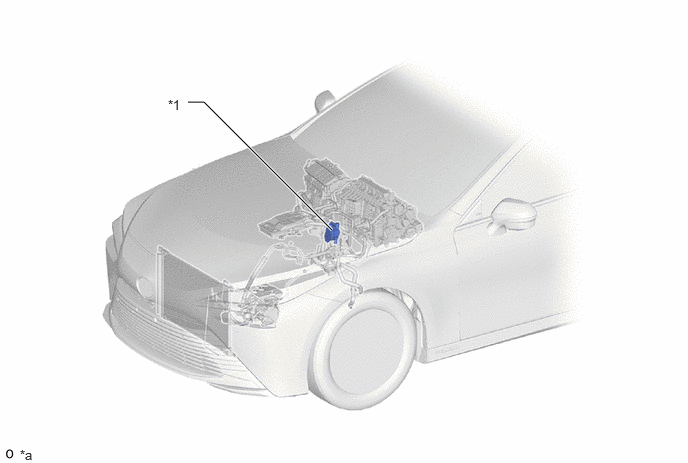
The three way valve (water valve assembly) is controlled by the air conditioning amplifier assembly.
b.
The use of the three way valve (water valve assembly) enables a coolant route configuration that is separated from the engine side.
c.
he three way valve (water valve assembly) is composed of parts such as the drive motor, potentiometer and switching valve.
3.458,2.396 2.125,1.063
2.125,1.063 1.958,1.063
true
1.75,1.01 2.094,1.167
0.344,0.156
10
false
*1
0.208,4.656 0.521,4.813
0.313,0.156
10
false
*a
| *1 | Three Way Valve (Water Valve Assembly)
·
Drive Motor ·
Potentiometer ·
Switching Valve |
- | - |
| *a | This illustration is an example only. | - | - |
OPERATION
a.
Passage Configuration
i.
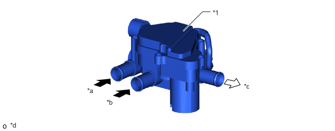
The air conditioning amplifier assembly detects the rotational angle of the switching valve from the potentiometer signals and rotates the switching valve with the drive motor to form coolant routes according to each control.
3.917,0.667 4.333,0.25
4.333,0.25 4.5,0.25
true
0.219,2.594 0.531,2.792
0.313,0.198
10
false
*d
4.552,0.188 4.865,0.385
0.313,0.198
10
false
*1
1.865,1.854 2.177,2.052
0.313,0.198
10
false
*a
2.281,2.104 2.594,2.302
0.313,0.198
10
false
*b
5.219,1.76 5.531,1.958
0.313,0.198
10
false
*c
| *1 | Three Way Valve (Water Valve Assembly) | - | - |
| *a | From FC Stack Assembly | *b | From Heater Radiator Unit Sub-assembly |
| *c | To Heater Water Pump (Water Pump with Motor Assembly) | *d | This illustration is an image. |

|
FC Coolant Inflow | 
|
FC Coolant Outflow |