METER / GAUGE / DISPLAY METER / GAUGE SYSTEM GENERAL GENERAL
OUTLINE
Combination Meter Assembly
The combination meter assembly has a built-in meter ECU and buzzer.
A multi-information display on which various kinds of information is displayed is integrated.
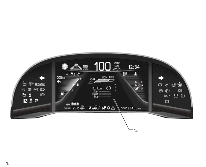
| *a | Multi-information Display | *b | The illustration is an example that shows the locations of the indicators. |
MAIN FEATURES
Multi-information Display
The multi-information display is located at the center of the combination meter assembly.
The multi-information display shows the following information:
| Item | Outline |
|---|---|
|
*1: Models with panoramic view monitor system *2: Models with road sign assist system |
|
| Indicator | ·
When the display conditions are met, the following indicators illuminate: -
SNOW Mode Indicator -
Blower Mode Indicator -
Br Mode Indicator -
RCD OFF Indicator*1 -
Traffic Sign*2 -
Lane Tracing Assist System Indicator -
Cruise Control Indicator (Constant Speed Control Mode) -
Cruise Control Indicator (Vehicle-to-Vehicle Distance Control Mode) -
Cruise SET Indicator -
ECO Mode Indicator -
SPORT Mode Indicator -
Ice Warning Indicator -
Low Fuel Level Warning Indicator -
High Coolant Temperature Warning Indicator -
Rear Seat Belt Warning |
| Information | ·
The following information can be displayed on the multi-information display by switching the tabs: -
Fuel Economy Tab -
Driving Assist System Information Tab -
Audio Information Tab -
Vehicle Information Tab -
Settings Tab -
Warning Message Tab |
| Dynamic Radar Cruise Control System / Lane Tracing Assist System State | Displays the operating state of the dynamic radar cruise control system and lane tracing assist system. |
| Outside Temperature | ·
The outside temperature is displayed. ·
When the outside temperature drops below 3°C (37°F), an ice warning flashes to warn the driver to drive with caution due to possibly icy road conditions. |
| Rear Seat Belt Warning Indicator | The state of wearing the rear seat belt is displayed. |
| Clock | The current time is displayed. |
| Shift Position Indicator | The current shift position is displayed. |
| ODO/TRIP Meter | The odometer, trip meter A or trip meter B is displayed. |
| Vehicle Power Source State | The vehicle power source state is displayed. |
| Light Control Rheostat | Meter panel luminance can be changed. |
| Fuel Level | Displays the current remaining fuel amount. |
| Estimated Distance to Empty | Displays the current estimated distance to empty. |
The following information can be displayed on the multi-information display by switching the tabs:
| Item | Outline |
|---|---|
|
*: Models with navigation system |
|
| Fuel Economy Tab | ·
The following items can be displayed: -
Fuel Consumption Graph -
Eco Guide |
| Driving Assist System Information Tab | ·
The following items can be displayed: -
Dynamic Radar Cruise Control System Information -
Lane Tracing Assist System Information -
Navigation System Informartion* |
| Audio Information Tab | The audio source or an audio track can be selected. |
| Vehicle Information Tab | ·
The following items can be displayed: -
System Status -
Energy Monitor -
Tire Pressure Warning System Information |
| Settings Tab | Various setting items can be displayed. |
FC System Indicator
An FC system indicator is provided to display the FC system output and regeneration status.
The FC system indicator is composed of 3 areas: the charge area, Eco area and power area.
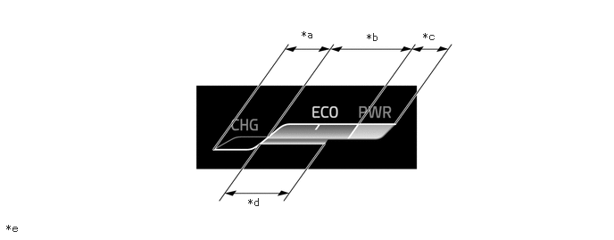
| *a | Charge Area | *b | Eco Area |
| *c | Power Area | *d | Recommended Accelerator Pedal Depression Amount |
| *e | The illustrations shown are examples only. | - | - |
| Area | Function |
|---|---|
| Charge | The charge area indicates when energy is being regenerated. |
| Eco | The eco area indicates when the vehicle is being driven in an eco-friendly manner. |
| Power | The power area indicates that the eco-friendly driving range is being exceeded (during full power driving, etc.). |
Eco Score
Eco score separates driving conditions into 3 patterns (Eco start, stable driving and Eco stopping), evaluates each on a 5-point scale, and displays a score out of 100 each time the vehicle is stopped.
| Start | Bar graph to display eco driving score when accelerating from stopped. |
| Cruise | Bar graph to display eco driving score when cruising. |
| Stop | Bar graph to display eco driving score when decelerating to stopped. |
| Score | Total eco driving score based on eco accelerator guidance. |
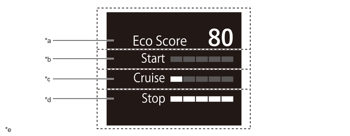
| *a | Score | *b | Start |
| *c | Cruise | *d | Stop |
| *e | The illustrations shown are examples only. | - | - |
- HINT:
- ·
When the power switch is on (READY), an eco driving score is provided for each individual cycle which spans from start to stop.
·When the power switch is turned off, the total eco driving score from power switch on (READY) to power switch off is displayed.