HYBRID / BATTERY CONTROL HYBRID CONTROL SYSTEM DETAILS HYBRID CONTROL
OPERATION
In the fuel cell vehicle, the electric power from the FC stack assembly and EV supply battery assembly are distributed in an optimal way according to a variety of driving conditions, realizing excellent vehicle performance including smooth starting and acceleration. Also, during deceleration the electric motor (traction motor) operates as a regenerative brake to convert braking force into electrical energy that is used for charging the EV supply battery assembly or powering FC related auxiliary components such as the FC air compressor with motor assembly.
The following items are examples of vehicle performance in response to a variety of driving conditions.
System start
When the brake pedal is depressed and the ignition switch is then pressed, the EV control ECU will start the system after first checking the results of the FC system check performed by the FC control ECU, the power source check, the shift position check, etc.
Charging while stopped
When the vehicle is stopped and the SOC is low, the FC stack assembly will generate electricity and charge the EV supply battery assembly.
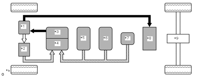
| *1 | Inverter with Converter Assembly | *2 | FC Air Compressor with Motor Assembly |
| *3 | FC Converter Assembly | *4 | FC Stack Assembly |
| *5 | No. 1 Hydrogen Tank Assembly | *6 | No. 2 Hydrogen Tank Assembly |
| *7 | No. 3 Hydrogen Tank Assembly | *8 | EV Supply Battery Assembly |
| *9 | Electric Motor (Traction Motor) | - | - |
| *a | Illustrations expressed in the image | - | - |

|
Electrical Power Path (DC) | 
|
Electrical Power Path (AC) |

|
Hydrogen | 
|
Compressed air (Oxygen) |
Starting to move / Driving with low load
Under normal conditions, when the vehicle starts to move, the electric motor (traction motor)s are powered by electrical energy from the EV supply battery assembly.
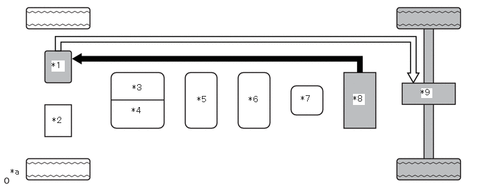
| *1 | Inverter with Converter Assembly | *2 | FC Air Compressor with Motor Assembly |
| *3 | FC Converter Assembly | *4 | FC Stack Assembly |
| *5 | No. 1 Hydrogen Tank Assembly | *6 | No. 2 Hydrogen Tank Assembly |
| *7 | No. 3 Hydrogen Tank Assembly | *8 | EV Supply Battery Assembly |
| *9 | Electric Motor (Traction Motor) | - | - |
| *a | Illustrations expressed in the image | - | - |
|
|
Electrical Power Path (DC) |
|
Electrical Power Path (AC) |
Steady Driving
During steady driving, electrical energy from the FC stack assembly is used to drive the electric motor (traction motor).
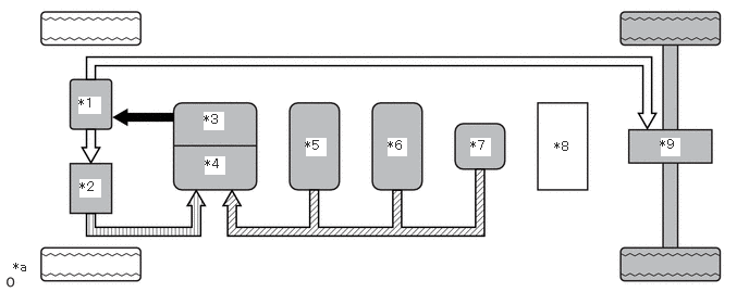
| *1 | Inverter with Converter Assembly | *2 | FC Air Compressor with Motor Assembly |
| *3 | FC Converter Assembly | *4 | FC Stack Assembly |
| *5 | No. 1 Hydrogen Tank Assembly | *6 | No. 2 Hydrogen Tank Assembly |
| *7 | No. 3 Hydrogen Tank Assembly | *8 | EV Supply Battery Assembly |
| *9 | Electric Motor (Traction Motor) | - | - |
| *a | Illustrations expressed in the image | - | - |
|
|
Electrical Power Path (DC) |
|
Electrical Power Path (AC) |
|
|
Hydrogen |
|
Compressed air (Oxygen) |
Acceleration
During acceleration, the electrical power from the FC stack assembly is increased, the boost ratio of the FC boost converter is made larger, and additional electrical energy is supplied from the EV battery to accelerate the vehicle.
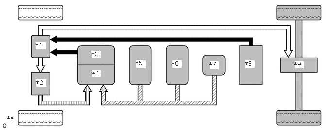
| *1 | Inverter with Converter Assembly | *2 | FC Air Compressor with Motor Assembly |
| *3 | FC Converter Assembly | *4 | FC Stack Assembly |
| *5 | No. 1 Hydrogen Tank Assembly | *6 | No. 2 Hydrogen Tank Assembly |
| *7 | No. 3 Hydrogen Tank Assembly | *8 | EV Supply Battery Assembly |
| *9 | Electric Motor (Traction Motor) | - | - |
| *a | Illustrations expressed in the image | - | - |
|
|
Electrical Power Path (DC) |
|
Electrical Power Path (AC) |
|
|
Hydrogen |
|
Compressed air (Oxygen) |
Deceleration / Braking
By using the drive force transmitted through the wheel to spin the electric motor (traction motor) and generate regenerative power, kinetic energy is converted into electrical energy to charge the EV supply battery assembly.
When the electrical energy produced from regenerative power generation cannot charge the EV supply battery assembly during deceleration, electrical energy produced from regenerative power generation is converted into kinetic energy or heat energy and consumed by FC auxiliary devices such as the FC air compressor with motor assembly.
In situations such as when FC auxiliary devices are used to warm up the FC system, the amount of regenerative power generation is decreased since power cannot be consumed by the FC auxiliary devices.
- HINT:
-
During regenerative braking, even when the FC stack assembly is not performing electrical generation, FC auxiliary devices may operate.
During braking, to ensure that braking force proportional to the brake pedal operation amount is achieved, cooperative control is performed together with the electronically controlled hydraulic brake system while the amount of energy to recover is decided.
When electrical energy produced from regenerative power generation cannot be used to charge the EV supply battery assembly, the braking force distributed to the hydraulic pressure brake is increased.
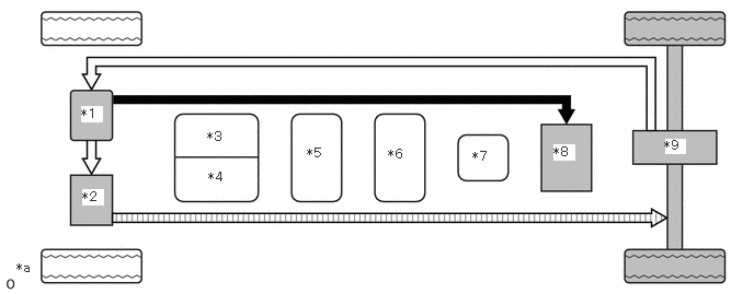
| *1 | Inverter with Converter Assembly | *2 | FC Air Compressor with Motor Assembly |
| *3 | FC Converter Assembly | *4 | FC Stack Assembly |
| *5 | No. 1 Hydrogen Tank Assembly | *6 | No. 2 Hydrogen Tank Assembly |
| *7 | No. 3 Hydrogen Tank Assembly | *8 | EV Supply Battery Assembly |
| *9 | Electric Motor (Traction Motor) | - | - |
| *a | Illustrations expressed in the image | - | - |
|
|
Electrical Power Path (DC) |
|
Electrical Power Path (AC) |
|
|
Compressed air (Oxygen) | - | - |
Driving in reverse
When driving in reverse, electrical power from the EV supply battery assembly is used to spin the electric motor (traction motor) in the opposite direction of that used in forward motion, which drives the vehicle in reverse.