FC CONTROL FC CONTROL SYSTEM CONTROL FC CONTROL
FUNCTION OF MAIN COMPONENTS
| Component | Function | |
|---|---|---|
| EV Control ECU | ·
Controls the amount of hydrogen and oxygen supplied to the FC stack assembly, and controls the power generation amount of the FC stack assembly ·
Sends FC compressor request values to the MG ECU built into the inverter with converter assembly and injector operation request values to the FC control ECU, based on the amount of required air and hydrogen calculated. ·
Controls the coolant flow rate and cooling fan speed based on the FC stack coolant temperature, and controls the FC stack coolant temperature. ·
Sends operation requests for each valve to the FC control ECU according to the outside air temperature, operates the FC air compressor with motor assembly and hydrogen recirculation pump assembly to control the amount of fluid contained in the FC stack assembly, and prevents parts such as the FC cell catalyst layer and pipes from freezing. |
|
| FC Control ECU | Receives requests from the EV control ECU, opens/closes each valve and operates the fuel injector assembly. | |
| FC Stack Assembly | FC Stack | Generates electrical energy by causing a chemical reaction between hydrogen fuel from the hydrogen tank and oxygen from the FC air compressor with motor assembly. |
| FC Stack Voltage Sensor | Detects the output voltage of fuel cells in the stack and transmits the value to the FC control ECU. | |
| FC Converter Assembly | FRB (FC Stack Main Relay) | Connects and shuts off the high voltage circuit from the FC stack assembly to the inverter with converter assembly, according to operation signals from the EV control ECU. |
| FRG (FC Stack Main Relay) | ||
| FRP (Precharge Relay) | ||
| FC Hydrogen Pump Inverter Assembly | Controlled by the EV control ECU, and supplies the electrical power that actuates the hydrogen recirculation pump assembly. | |
| FC Cooling Water Pump Inverter Assembly | Controlled by the EV control ECU, and supplies the electrical power that actuates the FC cooling water pump assembly. | |
| Hydrogen Recirculation Pump Assembly | Circulates the hydrogen supplied from the fuel injector assembly within the FC stack assembly. | |
| FC Air Compressor with Motor Assembly | ·
Supercharges the air that has passed the air cleaner and provides it to the FC stack assembly. ·
Driven by the inverter of the inverter with converter assembly. |
|
| Rotation Sensor | Detects the rotor position and speed of the FC air compressor rotor, and outputs it to the MG ECU built into the inverter with converter assembly. | |
| Temperature Sensor | Detects the temperature of the FC air compressor motor, and outputs it to the EV control ECU. | |
| Inverter with Converter Assembly | Based on the requested output value from the EV control ECU, controls the electrical power provided to the FCV transaxle with motor assembly and FC air compressor with motor assembly. | |
| FC Cooling Water Pump Assembly | Circulates the FC stack coolant, which cools the FC stack assembly and the air compressed by the FC air compressor with motor assembly. | |
| FC Water Release Switch | Enables the generated water inside the FC stack assembly and exhaust pipe to be drained at will. | |
| Combination Meter Assembly | Hydrogen Leak Warning Light | Illuminates when a hydrogen leak has been detected. |
| Buzzer | When there is a system malfunction, the buzzer sounds depending on the contents of the malfunction. | |
| Multi-information Display | Displays a warning message corresponding to each system malfunction. | |
SYSTEM CONTROL
Normal Control
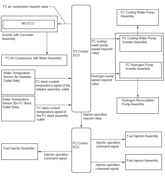
The EV control ECU calculates the required amount of oxygen and hydrogen, sends injector operation request values to the FC control ECU, and sends FC air compressor request values to the MG ECU built into the inverter with converter assembly. Additionally, it sends hydrogen pump speed request values to the FC hydrogen pump inverter assembly and ensures sufficient hydrogen for power generation.
The FC control ECU controls the fuel injector assembly based on injector operation requests from the EV control ECU, and controls the amount of hydrogen supplied to the FC stack assembly.
Based on the FC air compressor request from the EV control ECU, the MG ECU controls the FC air compressor with motor assembly, thus controlling the amount of oxygen provided to the FC stack assembly.
Freezing Prevention Control
When the vehicle is being driven or is parked, the FC control ECU controls the water content inside the FC stack to control the amount of water remaining in the exhaust pipe to prevent freezing in cold weather.
Necessity of preventing freezing
Freezing inside FC stack
Inside the cell of a fuel cell, when electrical energy is being generated, water is produced at the catalyst layer of the cathode (air electrode) of the fuel cell. If this water freezes, it will impede the flow of oxygen necessary for electrical generation, and generation efficiency will decrease. For this reason, it is necessary to prevent freezing.
Freezing of piping
The water produced during generation of electrical energy is drained from the exhaust pipe, but in some areas of piping where gas containing generated water flows, water can remain behind and freeze after IG off, impeding the flow of gas at the subsequent IG ON. This can lower generating efficiency or even stop generation completely if the piping is fully blocked. For this reason, it is necessary to prevent freezing.
Amount of Contained Fluid Control
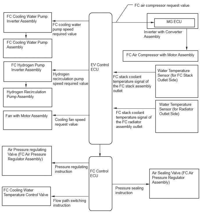
The EV control ECU provides control so that an appropriate amount of water will remain in the FC stack assembly. Particularly, if it determines that the outside air temperature will drop to 0 °C (32 °F) or lower while the vehicle is left until the next time it will be started, it adjusts the operating temperature of the FC stack assembly so that the amount of water inside the FC stack assembly will be reduced to a level that prevents performance below the freezing point from dropping when the vehicle is next started, and reduces the amount of excess water that is not needed.
When driving
The EV control ECU controls the operating temperature of the FC stack and evaporates water inside the FC stack assembly so that an appropriate amount of water will remain in the FC stack assembly. The speed of the FC cooling water pump assembly may change when the engine is idling in a low temperature environment.
When driving stops
When the vehicle has been left until the next time it will be started, if the EV control ECU determines that outside air temperature will drop to 0 °C (32 °F) or lower, the FC air compressor with motor assembly, hydrogen recirculation pump assembly and exhaust drain valve will be operated to release water from the FC stack assembly piping and exhaust pipe.
When parked
When the EV control ECU determines that the temperature of the FC stack assembly or other auxiliary devices will drop below 0 °C (32 °F) while the vehicle is parked after water was not drained when driving was completed, it operates the FC air compressor with motor assembly, hydrogen recirculation pump assembly and exhaust drain valve, and drains water from the FC stack assembly pipes and exhaust pipe.
Rapid Warmup Control
When the intake air temperature after passing through the intercooler is 0 °C (32 °F) or less or the FC stack assembly coolant temperature after passing through the FC stack assembly is 0 °C (32 °F) or less, the EV control ECU controls the amount of air supplied to the FC stack assembly and generates a large amount of heat in the FC stack, while the FC stack accelerates warmup in order to prevent generated fluid from refreezing.
During rapid warmup, maximum output will be restricted in order to prevent the generated water from causing the following problems.
Damage to cells of the FC stack due to generated water freezing.
During rapid warmup, the system is being driven to generate both electricity and heat, so at the same output level the FC current output is higher. Because the FC air compressor with motor assembly and hydrogen recirculation pump assembly are running at higher speed than normal, the operating sound becomes louder.
The system transitions to normal power generation mode once quick warmup has completed, the FC air compressor with motor assembly speed returns to normal.
Heat Sharing Control
The heat that is produced at the FC stack during electrical generation is used by the air conditioner system as a heat source for the heater. When the temperature of the FC stack coolant reaches a certain level or above, the FC stack coolant is taken from the FC stack into the air conditioner system, and so by including the heat produced in the FC stack assembly, in cold temperature regions the heating performance is improved and the electrical consumption of the electric heater sub-assembly is reduced while maintaining its heating performance.
Water Release Control
When the FC generates electrical energy, water is also produced. This generated water is released from the FC stack assembly to the exhaust pipe. The generated water released from the FC stack is intermittently released as water or water vapor.
- HINT:
-
The water release speed is determined by the discharge air amount, and when water release is taking place, the operating sound of the FC Air Compressor with Motor Assembly becomes louder.
Draining using FC water release switch
To prevent water spillage from the exhaust pipe in places like a garage or a multi-storey parking garage, a water release switch has been provided to enable the driver to force the system to drain water when the driver wants to do so.
Hydrogen Pressure Monitoring Control
Hydrogen pressure monitoring control by pressure sensor
Using the hydrogen secondary pressure sensor, hydrogen primary pressure sensor and hydrogen tank pressure sensor (outlet), the hydrogen pressures inside the FC system piping at startup are monitored, and if any of the measured pressures are lower than the specified values, a malfunction judgment is made, a message is displayed on the multi-information display in the combination meter assembly, and system operation stops. Also, if the pressure in the medium pressure piping decreases below the specified value while the FC system is in operation, an insufficient fuel judgment is made.
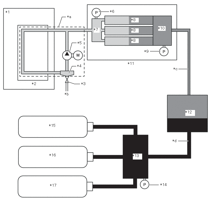
| *1 | FC Stack Assembly | *2 | FC Stack |
| *3 | Exhaust and Drain Valve | *4 | Gas-liquid Separator |
| *5 | Hydrogen Recirculation Pump Assembly | *6 | Hydrogen Secondary Pressure Sensor |
| *7 | Hydrogen Supply Secondary Pipe Sub-assembly | *8 | Fuel Injector Assembly |
| *9 | Hydrogen Primary Pressure Sensor | *10 | Hydrogen Supply Primary Pipe Sub-assembly |
| *11 | Hydrogen Supply Unit (Hydrogen Supply Pressure Regulator Assembly) | *12 | Hydrogen Supply Regulator |
| *13 | Hydrogen Tank Tube Joint Assembly (for Outlet Side) | *14 | Hydrogen Tank Pressure Sensor (for Outlet Side) |
| *15 | No. 1 Hydrogen Tank Assembly | *16 | No. 2 Hydrogen Tank Assembly |
| *17 | No. 3 Hydrogen Tank Assembly | - | - |
| *a | Hydrogen Circulation System | *b | To Exhaust Pipe |
| *c | Medium Pressure Pipe | *d | High Pressure Pipe |

|
Hydrogen secondary pressure sensor detection part | 
|
Hydrogen primary pressure sensor detection part |

|
Hydrogen tank pressure sensor (outlet) detection part | - | - |
Hydrogen leak detection by hydrogen detector
Hydrogen detectors are installed in the fuel cell unit compartment and on the upper No. 2 hydrogen tank assembly and upper No. 3 hydrogen tank assembly, and are used to detect hydrogen leaks from parts such as the vehicle pipe joints.
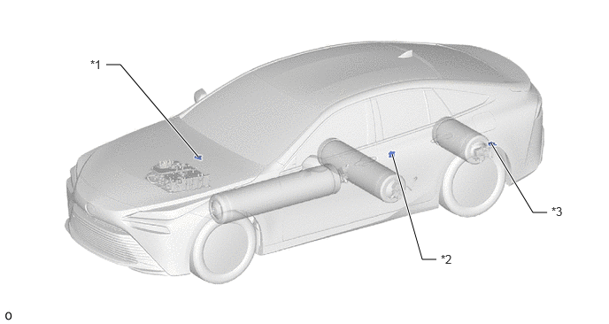
| *1 | Hydrogen Detector (for Fuel Cell Unit Compartment Side) | *2 | Hydrogen Detector (for No. 1, 2 Hydrogen Tank Assembly Side) |
| *3 | Hydrogen Detector (for No. 3 Hydrogen Tank Assembly Side) | - | - |