BATTERY / CHARGING SUB BATTERY SYSTEM CONTROL SUB BATTERY SYSTEM CONTROL
FUNCTION OF MAIN COMPONENTS
| Component | Function | |
|---|---|---|
| Shift Control Actuator Assembly | Locks and unlocks the parking lock mechanism. | |
| Luggage Room Relay Block Assembly | P CON MTR Relay | Supplies power to the shift control actuator assembly by signal from shift control ECU. |
| Inverter with Converter Assembly | DC-DC Converter | ·
Supplies electricity to the electrical components. ·
Supplies power to the shift control supply. |
| Auxiliary Battery | ||
| Shift Control Supply | Sub-battery ECU | ·
Controls the sub battery system function according to signals from the shift control ECU. ·
Detects the SOC (battery charging rate) and SOH (battery deterioration level) of the electric double-layer capacitor. ·
Automatically initiates and controls charging of the electric double-layer capacitor when the ignition switch is turned ON (IG). |
| DC-DC Converter | Performs voltage boost and step-down for charging and power supply of the electric double-layer capacitor. | |
| Electric Double-layer Capacitor | Supplies power to the electronic shift lever system during a power source malfunction. | |
| Backup Relay | Opens and closes the power source circuit between the DC-DC converter (inverter with converter assembly) and auxiliary battery or DC/DC converter. | |
| P CON MTR 2 Relay | Opens and closes the power source circuit between the DC-DC converter (inverter with converter assembly) and shift control actuator assembly. | |
| Shift Control ECU | ·
Controls the electronic shift lever system. ·
Detects the auxiliary battery voltage. ·
Sends a signal to the shift control supply when power supply from the auxiliary battery is lost, instructing the shift control supply to supply auxiliary power to the shift control ECU and shift control actuator assembly. |
|
| EV Control ECU | Controls the voltage generated by the DC-DC converter (inverter with converter assembly) according to voltage generation command signals from the shift control ECU. | |
SYSTEM CONTROL
Sub Battery System Control
The P CON MTR relay, P CON MTR 2 relay and backup relay are turned on and off according to the vehicle condition.
| Situation | P CON MTR Relay | P CON MTR 2 Relay | Backup Relay |
|---|---|---|---|
| Sleeping (Ignition Switch Off) | Off | Off | Off |
| Charging (Normally) | On | Off | On |
| Standby (Normally) | On | Off | On |
| Discharging (Normally) | Off | Off | Off |
| Backup Mode | Off | On | Off |
- HINT:
-
When the ignition switch is off, the P CON MTR relay, P CON MTR 2 relay and backup relay are turned off.
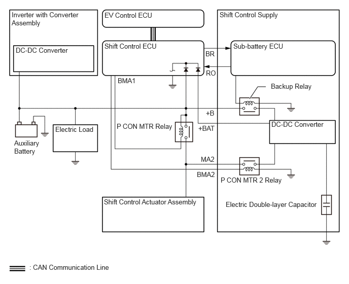
Sleeping (Ignition Switch Off)
The power supply for shift control supply is cut off.
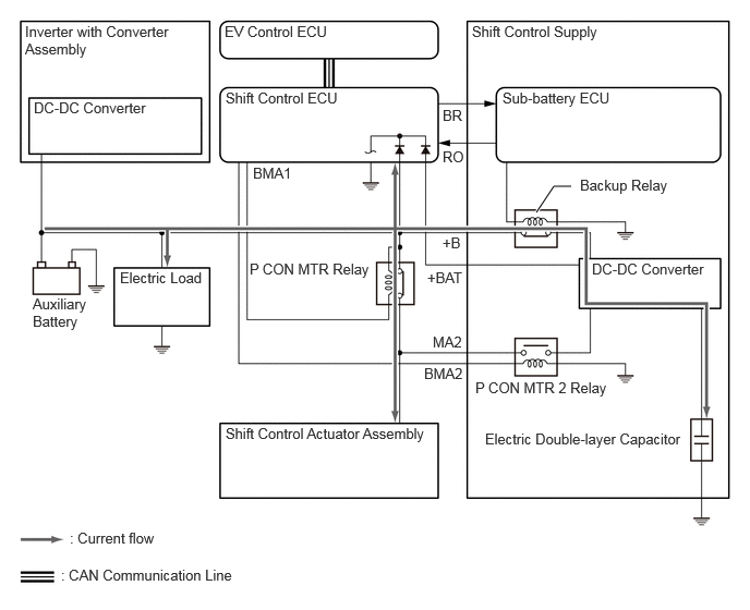
Charging (Normally)
When the ignition switch is turned ON (IG), charging of the electric double-layer capacitor is initiated automatically.
The auxiliary battery supplies power to achieve a stable power supply.
When charging the shift control supply, the sub-battery ECU calculates the State Of Charge (SOC) and SOH (battery deterioration level) of the electric double-layer capacitor. The sub-battery ECU sends backup relay open and close command signals to the backup relay based on the SOC value, and sends DC-DC converter (inverter with converter assembly) voltage generation command signals to the EV control ECU through the shift control ECU.
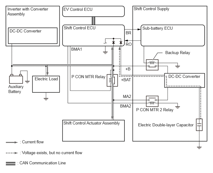
Standby (Normally)
The shift control supply is on standby to supply power after charging.
Discharging (Normally)
Turning the ignition switch off triggers the sleep mode, and the electric double-layer capacitor begins to discharge.
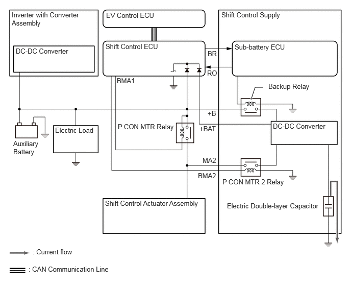
Backup Mode
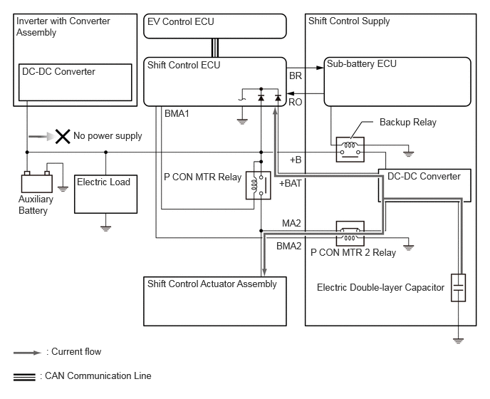
The shift control ECU and the sub-battery ECU both detect the power source voltage independently. If the power source voltage is less than the threshold value, the shift control ECU judges there to be a power source malfunction.
When it is judged that there is a power source malfunction, the sub-battery ECU turns the backup relay off and supplies power to the electronic shift lever system.
The shift control ECU and sub-battery ECU independently monitor the voltage to ensure power source malfunctions are detected even when only one of the ECUs judges a power source malfunction.
| ECU which Judged Power Source Malfunction | Operation |
|---|---|
| Shift Control ECU | The shift control ECU turns the directly connected P CON MTR 2 relay on and also sends a backup request signal to the sub-battery ECU. The P CON MTR 2 relay closes the backup power source circuits, which receive backup power from the electric double-layer capacitor which is then regulated by the DC-DC converter and then supply it to the shift control ECU and shift control actuator assembly. |
| Sub-battery ECU | Based on the backup request signal received from the shift control ECU, the sub-battery ECU turns the backup relay off and disconnects the power supply circuit from the DC-DC converter (inverter with converter assembly) and auxiliary battery. |
FAIL-SAFE
If the sub-battery ECU detects a malfunction in the shift control supply, the sub-battery ECU sends a signal to the shift control ECU, and the shift control ECU requests the warning message on the multi-information display and buzzer to alert the driver of the malfunction.
DIAGNOSIS
The FC control ECU will also store a Diagnostic Trouble Code (DTC). The DTC can be accessed through the use of the GTS. For details, refer to the Repair Manual.