FUEL HYDROGEN CONTROL SYSTEM CONTROL HYDROGEN CONTROL
FUNCTION OF MAIN COMPONENTS
| Component | Function | |
|---|---|---|
| EV Control ECU | ·
Controls the amount of hydrogen and oxygen supplied to the FC stack assembly, and controls the power generation amount of the FC stack assembly. ·
Sends FC compressor request values to the MG ECU built into the inverter with converter assembly and injector operation request values to the FC control ECU, based on the amount of required air and hydrogen calculated. ·
Controls the coolant flow rate and cooling fan speed based on the FC stack coolant temperature, and controls the FC stack coolant temperature. ·
Sends operation requests for each valve to the FC control ECU according to the outside air temperature, operates the FC air compressor with motor assembly and hydrogen recirculation pump assembly to control the amount of fluid contained in the FC stack assembly, and prevents parts such as the FC cell catalyst layer and pipes from freezing. |
|
| FC Control ECU | ·
Receives requests from the EV control ECU, and opens/closes each valve and operates the fuel injector assembly. |
|
| FC Stack Assembly | FC Stack | ·
Generates electrical energy by causing a chemical reaction between hydrogen fuel from the hydrogen tank and oxygen from the FC air compressor with motor assembly. |
| Hydrogen Recirculation Pump Assembly | ·
The hydrogen fuel that was supplied from an injector inside the FC stack assembly is circulated inside the FC stack assembly. |
|
| Hydrogen Supply Unit | Fuel Injector Assembly | ·
Controlled by the FC control ECU, adjusts hydrogen fuel pressure and supplies it to the FC stack assembly. |
| FC Converter Assembly | FC Cooling Water Pump Inverter Assembly | ·
Controlled by the EV control ECU, and supplies the electrical power that actuates the FC cooling water pump assembly. |
| FC Hydrogen Pump Inverter Assembly | ·
Controlled by the EV control ECU, and supplies the electrical power that actuates the hydrogen recirculation pump assembly. |
|
| Combination Meter Assembly | Hydrogen Leak Warning Light | ·
Illuminates when a hydrogen leak has been detected. |
| Master Warning Light | ·
When there is a system malfunction, the light illuminates depending on the malfunction. |
|
| Multi-Buzzer | ·
When there is a system malfunction, the buzzer sounds depending on the contents of the malfunction. |
|
| Component | Function | |
|---|---|---|
| Hydrogen Fuel Control ECU Assembly | ·
Based on the signal from the HV control ECU, controls the opening and closing of the hydrogen tank valve installed to the hydrogen tank. ·
Using infrared communication, transmits information such as vehicle tank capacity, tank internal gas pressure, temperature, etc. to the hydrogen dispenser. ·
Receives signals from the hydrogen tank temperature sensor installed on the hydrogen tank valve and the hydrogen tank pressure sensor (inlet) installed on the tube joint (inlet side) ·
Controls lock/unlock of fuel lid. |
|
| EV Control ECU | ·
Receives the hydrogen tank internal hydrogen fuel temperature from the hydrogen fuel control ECU assembly, and performs hydrogen fuel remaining compensation and hydrogen tank low temperature compensation. |
|
| Hydrogen Tank Assembly | Hydrogen Tank | ·
Employs a hydrogen tank made chiefly of carbon fiber reinforced plastic that can withstand high pressure of 70 MPa (713.8 kgf/cm2, 10150 psi). |
| Hydrogen Tank Valve Assembly | ·
Installed to each hydrogen tank, and opens and closes the hydrogen channels. |
|
| Hydrogen Tank Temperature Sensor | ·
Located inside the hydrogen tank valve, detects the hydrogen fuel temperature inside the hydrogen tank and transmits it to the hydrogen fuel control ECU assembly. |
|
| Hydrogen Supply Regulator Assembly | ·
Installed between the hydrogen tank and FC stack assembly, and reduces the pressure of the hydrogen fuel from the hydrogen tank to between 1.0 MPa and 1.5 MPa (10.2 kg/cm2 to 15.3 kg/cm2, 145 psi to 218 psi). |
|
| Hydrogen Inlet Receptacle Assembly | ·
Engages with the nozzle of the hydrogen dispenser, and supplies hydrogen fuel to the vehicle. Also prevents hydrogen leakage after filling (during driving). |
|
| Hydrogen Tank Pressure Sensor (for Inlet Side) | ·
Installed to the tube joint (inlet side), and transmits the hydrogen fuel pressure at the time of filling to the hydrogen fuel control ECU assembly. |
|
| Hydrogen Tank Pressure Sensor (for Outlet Side) | ·
Installed to the tube joint (outlet side) and transmits the hydrogen fuel pressure supplied from the hydrogen tank to the FC control ECU. |
|
| Hydrogen Fuel Control Transmitter | ·
Installed near the receptacle, and transmits vehicle information received from the hydrogen fuel control ECU assembly to hydrogen dispensers that are equipped with infrared communication functions. |
|
SYSTEM CONTROL
Hydrogen Supply / Circulation Control
The hydrogen fuel control ECU assembly supplies hydrogen fuel to the FC stack assembly.
The hydrogen fuel control ECU opens the electromagnetic valves of the hydrogen tank valves on the No. 1 hydrogen tank assembly, No. 2 hydrogen tank assembly and No. 3 hydrogen tank assembly and combines the hydrogen fuel in the tube joint (outlet side). The pressure is then reduced in the hydrogen supply regulator assembly and the fuel is supplied to the FC stack.
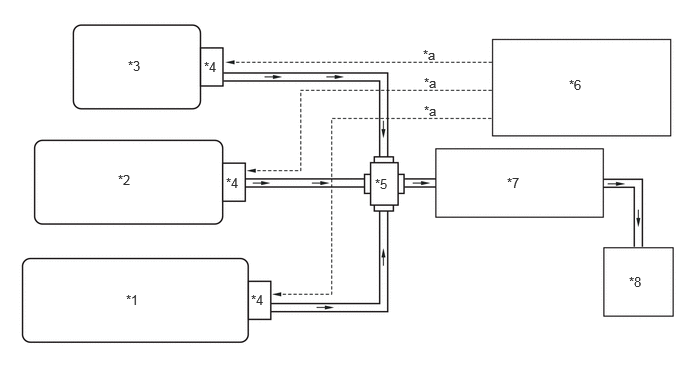
| *1 | No. 1 Hydrogen Tank Assembly | *2 | No. 2 Hydrogen Tank Assembly |
| *3 | No. 3 Hydrogen Tank Assembly | *4 | Hydrogen Tank Valve |
| *5 | Hydrogen Tank Tube Joint Assembly (for Outlet Side) | *6 | Hydrogen Fuel Control ECU Assembly |
| *7 | Hydrogen Supply Pressure Regulator Assembly | *8 | FC Stack Assembly |
| *a | Tank shut valve opening instruction | - | - |
The hydrogen circulation system of the FC stack assembly circulates the hydrogen fuel supplied from the injector to the hydrogen pump, and so the optimum hydrogen supply for FC stack electricity generation can be provided under all operating conditions.
The hydrogen circulation system of the FC stack assembly includes a gas-liquid separator and an exhaust drainage valve so that the generated water and nitrogen that could interfere with electricity generation are exhausted / drained from the hydrogen circulation system.
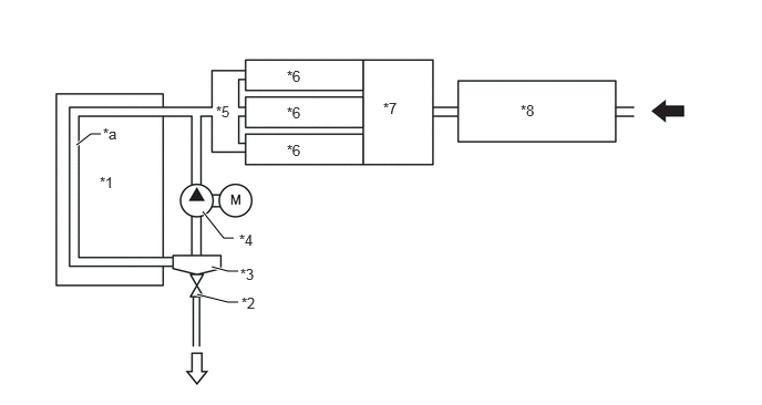
| *1 | FC Stack | *2 | Exhaust and Drain Valve |
| *3 | Gas-liquid Separator | *4 | Hydrogen Recirculation Pump Assembly |
| *5 | Hydrogen Supply Secondary Pipe Sub-assembly | *6 | Fuel Injector Assembly |
| *7 | Hydrogen Supply Primary Pipe Sub-assembly | *8 | Hydrogen Supply Regulator |
| *a | Hydrogen Circulation System | - | - |

|
From Hydrogen Tank | 
|
To Exhaust Pipe |
Injector control
The FC control ECU controls the injectors and supplies hydrogen fuel to the FC stack. Hydrogen gas that is regulated in the hydrogen supply regulator assembly to between 1.0 MPa (10.2 kgf/cm2, 145 psi) to 1.5 MPa (15.3 kgf/cm2, 218 psi) is then regulated in the injector to between 40 kPa (0.4 kgf/cm2, 5.8 psi) to 300 kPa (3.1 kgf/cm2, 43.5 psi). Based on the operating conditions, the number of injectors to actuate is controlled, and the quantity of hydrogen to supply to the FC stack is controlled.
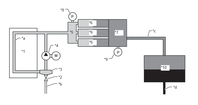
| *1 | FC Stack | *2 | Exhaust and Drain Valve |
| *3 | Gas-liquid Separator | *4 | Hydrogen Recirculation Pump Assembly |
| *5 | Hydrogen Supply Secondary Pipe Sub-assembly | *6 | Fuel Injector Assembly |
| *7 | Hydrogen Supply Primary Pipe Sub-assembly | *8 | Hydrogen Secondary Pressure Sensor |
| *9 | Hydrogen Primary Pressure Sensor | *10 | Hydrogen Supply Regulator |
| *a | Hydrogen Circulation System | *b | To Exhaust Pipe |
| *c | Medium Pressure Pipe | *d | High Pressure Pipe |

|
40 kPa to 300 kPa (0.4 kgf/cm2 to 3.1 kgf/cm2, 5.8 psi to 43.5 psi) | 
|
1.0 MPa to 1.5 MPa (10.2 kg/cm2 to 15.3 kg/cm2, 145 psi to 218 psi) |

|
70 MPa (713.8 kgf/cm2, 10150 psi) | - | - |
Hydrogen Pump Control
The EV control ECU takes information about FC stack electrical generation amount, electrical current value, etc. from the FC boost ECU (FC stack assembly) and controls the hydrogen pump so that the circulating hydrogen amount is appropriate to operating conditions.
Hydrogen filling control
Hydrogen filling
The hydrogen fuel from the hydrogen dispenser passes from the receptacle through the hydrogen tank tube assembly, branches at the hydrogen tank tube joint (for Inlet side), presses open the check valves of the hydrogen tank valves on the No. 1 hydrogen tank, No. 2 hydrogen tank and No. 3 hydrogen tank is filled into the tanks.
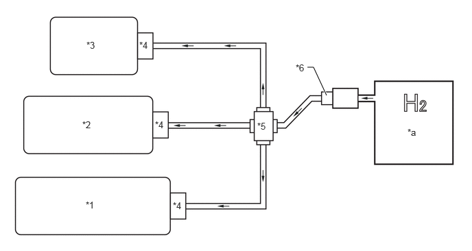
| *1 | No. 1 Hydrogen Tank | *2 | No. 2 Hydrogen Tank |
| *3 | No. 3 Hydrogen Tank | *4 | Hydrogen Tank Valve |
| *5 | Hydrogen Tank Tube Joint (for Inlet Side) | *6 | Hydrogen Inlet Receptacle |
| *a | Hydrogen Dispenser | - | - |
Infrared communication
The hydrogen fuel control ECU assembly uses infrared communication to transmit the hydrogen tank volume, the temperature inside the hydrogen tank and the pressure inside the hydrogen tank tube joint (for Inlet side) during hydrogen fuel filling, via the hydrogen fuel control transmitter, to the hydrogen dispenser.

| *1 | Hydrogen Fuel Control Transmitter | - | - |
- HINT:
-
When filling hydrogen fuel from a hydrogen dispenser supporting infrared communication, hydrogen fuel filling is performed according to vehicle conditions.
- ·
During hydrogen fuel filling, the flow of fuel may cause hissing, whistling, or other sounds of gas flowing to be heard from behind the rear seat.
·The time needed for filling and the amount of fuel filled into the tank may differ depending on the equipment at the hydrogen station. Some filling equipment may not completely fill the tank, reducing the distance that can be traveled until the next refueling.
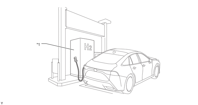 2.677,1.813 1.667,1.583 1.667,1.583 1.5,1.583 true 1.323,1.531 1.635,1.729 0.313,0.198 10 false *1
*1 Hydrogen Dispenser - -
Fuel lid open / close position control
To prevent the vehicle from moving suddenly during hydrogen fuel filling, when the fuel lid is open, the system cannot be set to READY ON. In addition, when the system is in READY ON, the fuel lid will not open even if the fuel lid opening is pressed.
- HINT:
-
If the lid is not fully closed, the system will not enter READY ON.
The fuel lid with motor lock assembly has a switch to detect opening and closing. The open/close status of the fuel lid is transmitted to the EV control ECU.

| *1 | Fuel Lid with Motor Lock Assembly | - | - |